Article Text

Abstract
Background: Occupational head exposure to radiation in cardiologists may cause radiation induced cataracts and an increased risk of brain cancer.
Objective: To determine the effectiveness of 0.5 mm lead equivalent caps, not previously used in invasive cardiology, in comparison with a 1.0 mm lead equivalent ceiling mounted lead glass screen.
Design: An anthropomorphic Alderson-Rando phantom was used to represent the patient. Scatter entrance skin air kerma to the operator position (S-ESAK-O) was measured during fluoroscopy for all standard angulations and the S-ESAK-O per dose–area product (DAP) calculated, as applied to the phantom.
Results: Measured mean (SD) left/right anterior oblique angulation ratios of S-ESAK-O without lead devices were 23.1 (10.1), and varied as a function of tube angulation, body height, and angle of incidence. S-ESAK-O/DAP decreased with incremental operator body height by 10 (3)% per 10 cm. A 1.0 mm lead glass shield reduced mean S-ESAK-O/DAP originating from coronary angiography from 1089 (764) to 54 (29) nSv/Gy × cm2. A 0.5 mm lead cap was effective in lowering measured levels to 1.8 (1.1) nSv/Gy × cm2. Both devices together enabled attenuation to 0.5 (0.1) nSv/Gy × cm2. The most advantageous line of vision for protection of the operator’s eyes was ⩾ 60° rightward.
Conclusions: Use of 0.5 mm lead caps proved highly effective, attenuating S-ESAK-O to 2.7 (2.0) × 10−3 of baseline, and to 1.2 (1.4) × 10−3 of baseline where there was an additional 1.0 mm lead glass shield. These results could vary according to the x ray systems used, catheterisation protocols, and correct use of radiation protection devices.
- dosimetry
- radiation safety
- radiation exposure
- DAP, dose–area product
- ESAK, entrance skin air kerma
- ESD, entrance skin dose
- LAO, left anterior oblique
- PA, posterior-anterior
- RAO, right anterior oblique
- S-ESAK-O, scatter entrance skin air kerma to the operator position
Statistics from Altmetric.com
- DAP, dose–area product
- ESAK, entrance skin air kerma
- ESD, entrance skin dose
- LAO, left anterior oblique
- PA, posterior-anterior
- RAO, right anterior oblique
- S-ESAK-O, scatter entrance skin air kerma to the operator position
No dose of radiation may be considered safe or harmless.1 All medical exposure for radiodiagnostic purposes should be kept “as low as reasonably achievable”,2,3 and “shielding, attached to either the equipment or the operator, should be used as completely as possible without encumbering the examining physician or . . .jeopardising the welfare of the patient”.4 Nevertheless, practising interventional cardiologists are reported to receive an annual average x ray dose of 1.7 mSv with the use of a thyroid shield, and 3.5 mSv without this protection (both figures include the use of a lead apron).5 Their effective dose per procedure varies between 9–50 μSv.6–8 Without lead protection, the operator’s eyes receive a mean (SEM) entrance skin dose of 165 (97) μSv per coronary angiography session.1,4,9–12 The use of lead eyeglasses lowers this level to 37 (15) μSv.9,11 The annual head dose sustained by cardiologists may reach 60 mSv a year, and may in some cases exceed the occupational limit of 150 mSv a year recommended for the lens of the eye.13 There is current consideration of the risks of radiation induced cataracts8,14 and malignancy, particularly brain cancer.5,15 Until now operators have not used personal protective garments to shield their forehead and brain. The goal of our study was to determine the effectiveness in invasive cardiology of lead equivalent caps 0.5 mm thick, and to compare this new type of protection with an improved 1.0 mm lead equivalent glass overcouch shield.
METHODS
Definitions
Patient’s entrance skin air kerma (ESAK) is the dose to the air in the entrance plane of the patient without backscatter. Entrance skin dose (ESD) includes backscatter and is appropriate for characterisation of deterministic risks for skin lesions. Both are measured in Grays (Gy = J/kg). Dose–area product (DAP) is the product of the area of the cross section of an x ray beam and the air kerma averaged over that cross section. The unit is Gray square centimetre (Gy × cm2). S-ESAK-O is the scatter entrance skin air kerma to the operator position caused by stray radiation, which is defined as the sum of the following: primary scatter emitted from the patient in all directions, secondary scatter reflected from the walls, and the small fraction of tube housing leakage.
DAP was measured for 122 patients as well as at an anthropomorphic Alderson-Rando phantom. In a second step, we measured S-ESAK-O at this phantom, representing the patient, during fluoroscopy for all standard angulations and calculated S-ESAK-O per DAP.
Equipment
We employed a digital, single arm Advantx LC+ undercouch tube and overcouch image intensifier system (GE Medical Systems, Fairfield, Connecticut, USA) with the following installed in the x ray beam: 0.1 mm copper filter, 2.9 mm aluminium filter, and—throughout all measurements—an antiscatter grid. Under conditions of focus image intensifier distance of 1 m, and for a copper absorber 2 mm thick, the image intensifier entrance dose rates during fluoroscopy were 0.21 μGy/s for the 23 cm image intensifier field and 0.30 μGy/s for the 17 cm field. During cine acquisition (12.5 frames/s), these values were 0.08 μGy/frame (23 cm field). The DAP was measured by an ionisation diamentor, calibrated in situ on the x ray tube (reliability for repetition < 3%; total uncertainty for linearity (60–150 kV) < 5% (M4, PTW, Freiburg, Germany)).
The electrical charge generated in the ionisation chamber was equivalent to the DAP (Gy × cm2) and accordingly was directly proportional to the collimated radiation beam passing the cross sectional chamber area as well as the patient’s body surface area. The company’s product specifications declare that the attenuation of the carbonaceous table, including the table cover (Omega 4, type 2181400, GE, Buc cedex, France), is equivalent to 1.2 mm aluminium, and that the correction factors at 70–90 kV are 1.10 for direct lateral exposures and 0.97 for undercouch exposure perpendicular to the couch.
Complete radiation protection (as supplied by MAVIG, Munich, Germany) was achieved by an articulated ceiling screen (60 × 75 cm), lengthened by a flap beside the table (21 × 80 cm); a longitudinal table mounted lead drape (60 × 80 cm), enhanced by a top shield (60 × 20 cm); and a lead cover around the phantom’s (patient’s) thighs. Each shield showed 1.0 mm lead equivalence (fig 1). The operator used a cap (Burkhart Roentgen International, St Petersburg, Florida, USA), glasses, apron, and collar (MAVIG, Munich, Germany), all with 0.5 mm lead equivalence (fig 2). The lead cap weighs approx 1140 g and offers acceptable wearing comfort.
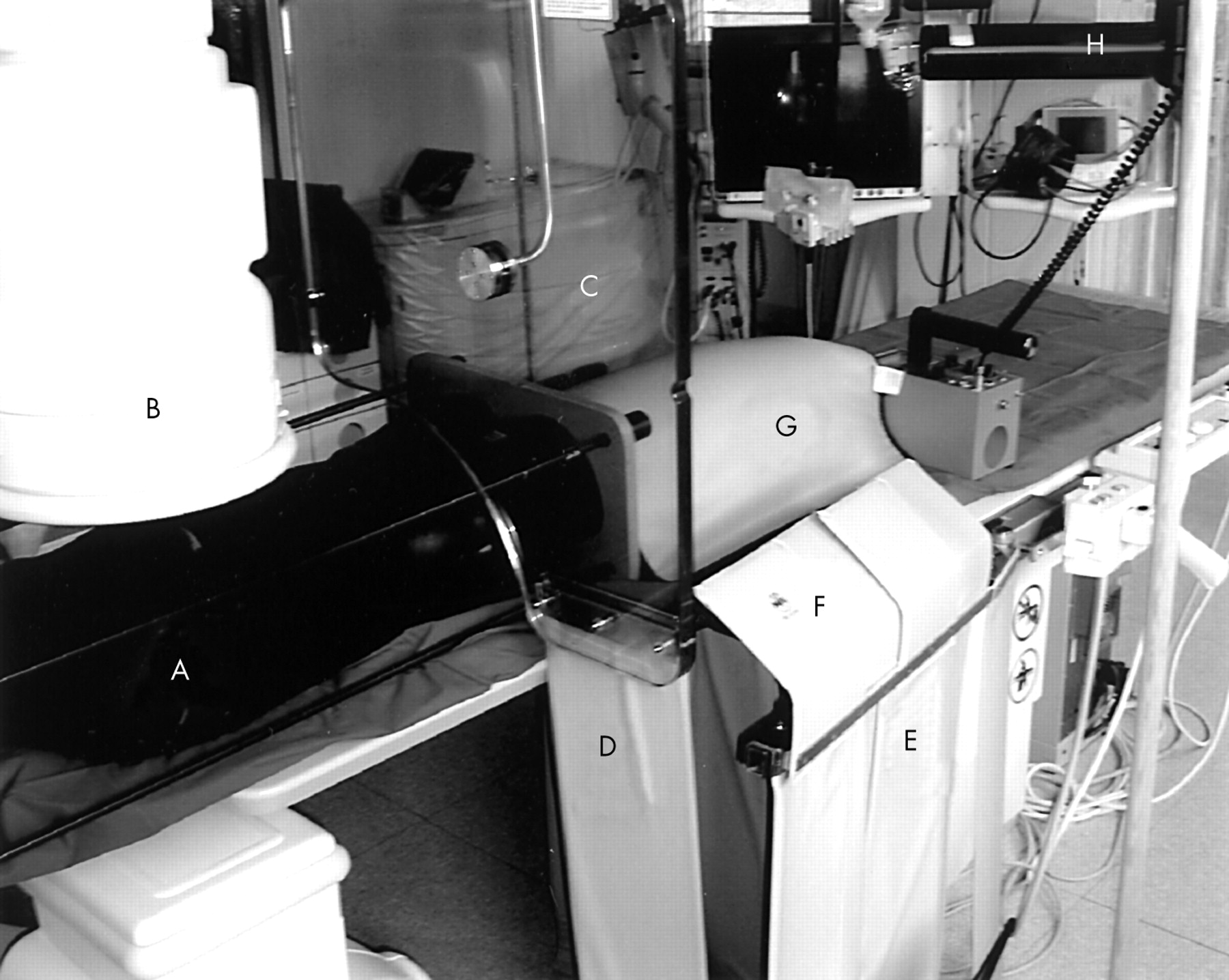
Position of Rando phantom (A); image intensifier (B); articulated ceiling screen (C), lengthened by a lead flap beside the table (D); longitudinal table mounted lead drape (E), enhanced by a top shield (F); and lead cover around the phantom’s thighs (G). The detector for scatter radiation in operator’s position (H) is directed towards the left side at an angle of incidence of −40°.
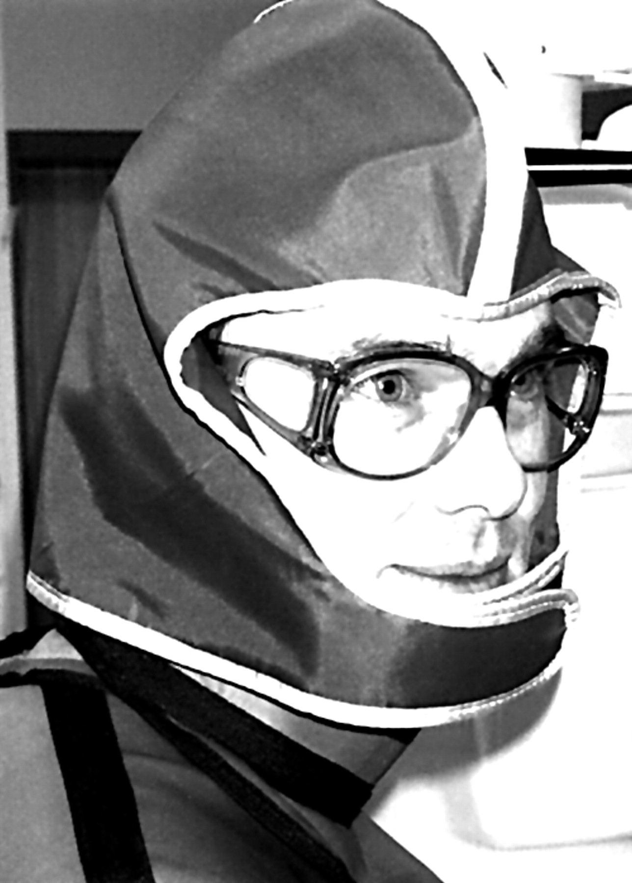
Protective garments with 0.5 mm lead equivalency: cap, glasses, collar, and apron.
Cardiac catheterisation procedures
One interventionist performed 122 diagnostic catheterisations with femoral access. We documented total DAP, DAP from cinematography (DAPC) and fluoroscopy (DAPF), the number of cinegraphic frames, and the time adjusted cinegraphic dose area product per frame. The patients’ mean (SD) age was 65 (8) years, 56% were male and 44% female, and their body mass index was 28 (4) kg/m2.
Characterisation of the patients’ in vivo conditions using a Rando phantom
The first methodological step was to validate the assessment of DAP obtained with the phantom with that received by a patient in an analysis of 122 coronary angiographic examinations. The mean patient DAPC/frame (17 cm intensifier field) obtained with the phantom did not differ significantly from that measured in vivo: 21.6 (7.7) v 24.0 (7.6) Gy × cm2 (p > 0.38), respectively. Using straight line regression, the correlation coefficient for all the various tube angulations was 0.91 (fig 1).
The second step was to correlate stray radiation to the operator with the DAPs measured on the phantom. The correlation coefficient was 0.99 between S-ESAK-O and DAP in 0°/0° posterior-anterior (PA) tube angulation at a table height of 95 cm, and with a dosimeter height of 100 cm at a distance of 100 cm from the isocentre. In agreement with other research, S-ESAK-O/DAP increased slightly with kV and field size (diameter 13–23 cm).16,17 In order to diminish the investigator’s radiation exposure, we undertook further scatter radiation measurements in fluoroscopy mode.
Data collection
We conducted measurements of fluoroscopy scatter radiation (μSv/h) at a male anthropomorphic Alderson-Rando phantom, using a Szintomat 6134 A system (Automess, Ladenburg, Germany). The system was calibrated for a dose intensity range of 100 nSv/h to 100 mSv/h. For an incident angle of 45°, the measured radiation exposure uncertainty was < 10%. At an operator’s position 100 cm from the isocentre (60 cm adjacent to and 80 cm caudally to the tube), we measured S-ESAK-O in 10 cm increments within a height range of 140–200 cm (seven positions), for all 10 standard tube angulations of coronary angiography (fig 1) and for all 11 angles of incidence to the operator (fig 3: −120°, −90°, −60°, −40°, and −20° to the left; 0°; and +20°, +40°, +60°, +90°, and +120° to the right of the operator’s front).
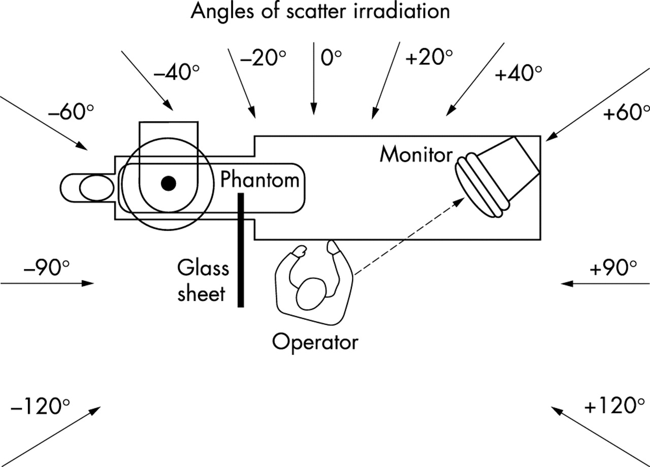
Position of tube, patient’s couch, and interventional operator, as well as angles of incidence of the scatter radiation to the operator: −120°, −90°, −60°, −40°, and −20° from the left side; 0°; and +20°, +40°, +60°, +90°, and +120° from the right side to the operator’s front.
Measurements were done in four steps: without any radiation protection; with an articulated, ceiling mounted 1.0 mm lead glass screen lengthened by the lead flap; with a helmet of 0.5 mm lead equivalence; and with both protection devices together (fig 2). We accordingly undertook a total of 3080 (7 × 10 × 11 × 4) individual measurements.
With measurements based on DAP per second and applied to the phantom, we calculated the ratio of S-ESAK-O to DAP at all heights for each angulation and angle of incidence to the operator. We then took into account the partial DAP contributions of the respective tube angulation to the overall in vivo DAP (6.5 Gy × cm2) obtained for the patients during coronary angiography.12 On this basis, we finally computed the local scatter-ESAK to the operator (S-ESAK-O) per applied Gy × cm2 during one coronary angiography session, in 10 cm increments within the height range of 140–200 cm. Under these conditions we analysed the efficacy of the ceiling mounted 1.0 mm lead glass screen lengthened by the lead flap, of a helmet of 0.5 mm lead equivalence, and of both protection devices together.
We used Student’s t test to verify differences in continuous variables and expressed the significance at a probability level of p = 0.05.
RESULTS
Fluoroscopic local scatter radiation exposure to the operator’s head
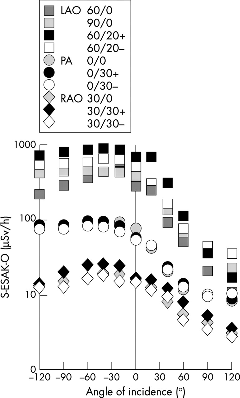
The primary scatter ESAK to the operator’s unprotected head (170 cm body height) under conditions of low level fluoroscopy (image intensifier entrance dose rate of 0.30 μGy/s for the 17 cm field) was highest for left anterior oblique (LAO) tube angulations (fig 4). Posterior-anterior (PA) angulations induced lower S-ESAK-O, and right anterior oblique (RAO) projections, the least. Cranial angulations (black symbols in the figures) apparently induced slightly, but not significantly, higher S-ESAK-O levels than caudal angulations (white symbols). Mean (SD) S-ESAK-O ratios were 23.1 (10.1) for LAO/RAO, 6.4 (2.0) for LAO/PA, and 3.5 (1.2) for PA/RAO angulations. The greatest scatter ESAK to the operator’s position was in the form of irradiation from the tube direction of −40° to −60° on the operator’s left, but also from 0° and a direction slightly to the right. Scatter radiation from +60° to +120° on the right side, however, was much lower.

Dependence of primary S-ESAK to the operator’s unprotected head (μSv/h) during low level fluoroscopy on tube angulation and angle of radiation incidence. LAO, left anterior oblique; PA, posterior-anterior; RAO, right anterior oblique; S-ESAK-O, scatter entrance skin air kerma to the operator.
Benefit of 1.0 mm lead screen and 0.5 mm lead cap
Overall in vivo DAP to patients during coronary angiography (n = 112) is the sum of all partial DAPs applied to them for the various tube angulations.18 We multiplied these partial in vivo DAPs by the S-ESAK-O per Gy × cm2, applied to the Rando phantom, for each respective tube angulation. The sum of these partial products represents the S-ESAK-O that reaches the operator from various angles of incidence during coronary angiography within a range of 140–200 cm body height. Dividing this value by the mean overall DAP of a coronary angiography, we obtained the mean S-ESAK to the operator per Gy × cm2 applied to the patient during coronary angiography (figs 5 and 6). Scatter ESAK to the operator’s eyes without radiation protection was much higher at a line of vision of −120° to 0° to the operator’s left than was scatter ESAK coming from ⩾ +60° to the right side. The operator will be exposed, over the range of 140–200 cm body height, to mean (SD) levels of 2.1 (0.5) μSv/Gy × cm2 from the left, and to less than 240 (40) nSv/Gy × cm2 from the right lines of vision ⩾ +60°. As measurement points rose along the operator’s height, the mean (SD) local operator radiation exposure decreased by 10 (3)% per 10 cm (fig 5).

Scatter ESAK-O per dose–area product, applied to the phantom during coronary angiography (nSv/Gy × cm2), as an inverse function of body height.
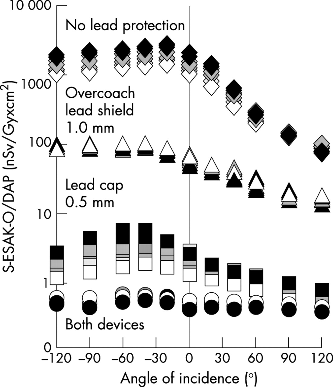
Scatter ESAK-O per dose–area product, applied to the phantom during coronary angiography (nSv/Gy × cm2), as a function of body height (140 cm (black symbols) . . . 200 cm (white symbols)) and angle of radiation incidence within −120° to +120° to the operator’s front. Effect of a 1.0 mm lead equivalent over couch shield, of a 0.5 mm lead equivalent cap, and of both devices together.
A 1.0 mm lead glass shield reduced mean (SD) S-ESAK-O/DAP from coronary angiography from 1089 (764) to 54 (29) nSv/Gy × cm2, depending on angle of incidence and body height. A 0.5 mm lead cap was effective in lowering measured levels to 1.8 (1.1) nSv/Gy × cm2. Both devices together achieved attenuation to 0.5 (0.1) nSv/Gy × cm2 (fig 6).
Dependence of operator’s scatter radiation exposure on line of vision
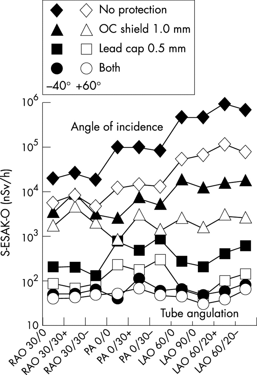
To enable the patient to follow the interventional procedure, the monitors in many catheterisation laboratories are positioned in a line of vision of −40° to the operator’s left. Regardless of tube angulation and of the absence or quality of lead protection, this line of vision (fig 7, black symbols) occasions higher S-ESAK-O levels to the operator’s eyes and brain than does looking to the right at an angle of incidence of +60° (fig 7, white symbols). With application of the protective devices, the ranking of radiation exposure according to tube angulation was no longer LAO > PA > RAO as demonstrated with no protection (black and white diamonds). Using both the glass shield and personal protection devices in the form of glasses and cap, scatter exposure to the operator’s eyes and brain during fluoroscopy while looking to the right (+60°) will be reduced for all tube angulations to similar mean S-ESAK-O levels within 30–67 nSv/h (white circles). The lower parts of the operator’s face unprotected by lead will be exposed to radiation levels of 800–4500 nSv/h with an overcouch lead glass shield (white triangles), and to 4500–110 000 nSv/h without this protection (white diamonds).
S-ESAK-O (nSv/h), as a function of tube angulation without lead protection (diamonds), and with the use of a 1.0 mm overcouch lead glass screen (triangles), of a 0.5 mm lead cap (squares), and of both devices together (circles). Effect of line of vision and monitor position in −40° tube direction (black), and +60° to the operator’s right side (white).
DISCUSSION
Primary scatter ESAK to the operator’s unprotected head is highest for left anterior oblique (LAO) tube angulations. This configuration is typically employed in invasive cardiology to document left main stem bifurcation (caudal LAO 60/20 spider view), the left anterior descending coronary artery (LAO 90/0), the bifurcation in the left anterior descending artery, and the diagonal branch (cranial LAO 60/20), and the left ventricle (LAO 60/0). Right anterior oblique (RAO) projections occasion the least radiation exposure. Mean S-ESAK-O ratios of LAO/RAO angulations to the operator’s brain were within 4.6 to 38.2, and ranged above reported ratios—that is, 2.6 to 12.4 with respect to total body height.18,19 Cardiologists should consequently limit fluoroscopic LAO projections and shorten cinegraphic LAO documentation whenever possible. The highest S-ESAK-O is of course emitted from the tube direction to the operator’s left, whereas scatter radiation from > +60° to the right is much lower. In order to protect lenses of the eyes and the brain, operators should attempt to work with monitors positioned to the right (fig 3).
In this study we measured mean S-ESAK-O/DAP levels of 2.1 (0.5) μSv/Gy × cm2 irradiating from the isocentre direction, with calculations based on all tube angulations used during coronary angiography. These results were significantly lower than the occupational doses of 8.4 μSv/Gy × cm2 reported for a modern catheterisation system.12 However, several methodological differences explain this higher stray radiation/DAP measured by other researchers. The distance to the isocentre in other studies was ⩽ 75 cm (v 100 cm in our catheterisation laboratory), dose measurements were done at 150 cm (170 cm in our laboratory), and operators did not consistently use low level modes as practised in the present study. For comparable circumstances with the operator’s position at a distance of 1 m to the isocentre, for 150 cm above ground, and for LAO 90°/0° tube angulation, our determined stray radiation level of 4.7 μSv/Gy × cm2, measured towards the isocentre, correlates well with published stray radiation levels of 4–8 μSv/Gy × cm2 for this exposure intensive tube angulation.8,20
Modern coronary angiography and percutaneous transluminal coronary angioplasty, as most recently reported, induce mean (SEM) DAPs of 62 (28) Gy × cm2,21–26 and 85 (34) Gy × cm2,21,23,24,27 respectively. The patient’s DAPs and, in turn, the operator’s stray radiation vary greatly, depending on the x ray system employed, the operator’s experience, the protocol, and the efficacy and acceptance of protection devices. Unfortunately, “. . . many interventionists are not aware of the potential for injury from procedures, their occurrence, or simple methods for decreasing their incidence utilising dose control strategies.”8 Staff doses can be considerably increased if inappropriate x ray equipment or inadequate personal protection is used.12
Operators in a high volume catheterisation laboratory with a cumulative yearly workload of 1000 interventions, 40% of them typically being percutaneous transluminal coronary angioplasties, will subject their patients to a yearly cumulative radiation load of approximately 71 200 Gy × cm2. Without lead protection, they will be exposed over the range of 140–200 cm body height to mean (SD) levels of 146 (38) mSv from the left sided lines of vision, down to less than 17 (3) mSv from right sided angles of incidence of ⩾ +60°. Greater body height reduces the mean operator’s head exposure by approximately 1%/cm (fig 5). In good agreement with these calculations, the published mean entrance skin dose per coronary angiography to the lens of the operator’s eye under the same workload would produce a mean (SEM) local annual radiation exposure of more than 165 (97) mSv.1,4,9–12 This level reflects the fact that coronary interventions typically include not only coronary angiography but also radiation intensive percutaneous transluminal coronary angioplasty. Such exposure levels exceed the recommended occupational limit of 150 mSv/year for the lens of the eye. This fact has prompted discussion in the literature of the relevance of these levels with respect to above normal frequencies of cataract development and brain cancer observed among interventionists.13,15
These data should motivate cardiologists to make every effort to reduce such high exposure to their eyes and brain by application of the means of protection examined in the present study—that is, the use of both a 1.0 mm lead screen and a 0.5 mm lead cap. This recommended solution achieved a reduction of mean S-ESAK-O levels to 1.2 (1.4) × 10−3 of baseline. However, these results can vary according to the x ray systems used, the catheterisation protocols, and the operator’s correct use of the individual radiation protection devices.
Unexpectedly, a cap with only 0.5 mm lead equivalence was more protective than an overcouch shield with 1.0 mm lead equivalence (fig 6). This finding indicates that a significant amount of secondary scatter radiation, reflected from the laboratory walls, may reach the operator’s head, despite the presence of a ceiling mounted lead glass shield designed to protect the face and head from primary scatter radiation from the patient.
Without any protection, or with 1.0 mm lead equivalent overcouch protection alone, the monitor position typically determines the operator’s predominant line of vision in invasive cardiology. Regardless of tube angulation, the lowest S-ESAK-O will typically occur in a line of vision toward the foot of the table (fig 7). The use of additional 0.5 mm lead equivalent caps and glasses reduces such dependence on monitor position and the operator’s line of vision. Under conditions of optimised radiation protection as outlined here, the operator’s mean head exposure levels during fluoroscopy will range below the individual effective dose from environmental background radiation of 200–300 nSv/h.
At the same time, we did not take into account the S-ESAK-O fraction resulting from scattering around personal lead garments from the unprotected lower parts of the operators’ face, up to their brain and eyes. Anatomical and technical circumstances render these levels hardly measurable with the ESAK acquisition systems currently in use. Even under conditions of optimised radiation protection of the head region as outlined in this study, looking toward the foot of the table (+60°) nevertheless exposes the lead-unprotected lower parts of the operator’s face to considerable mean radiation levels—that is, to 2300 (1050) nSv/h (white triangles) and 35 600 (37 100) nSv/h (white diamonds) in the presence and absence of an overcouch lead glass shield, respectively. We determined that looking towards the tube exposes the lower parts of the face to levels 4–10 times greater than does looking rightwards (fig 7). Optimal minimisation of this fraction would be possible through an improved lead helmet, including protection of nose and chin regions. The additional efficacy of a lead cap with respect to protection from stray radiation, as evidenced in this study, may encourage interventionalists to use one, especially as this cap is hardly more uncomfortable to wear than the conventionally recommended lead apron and lead glasses.