Article Text

Abstract
OBJECTIVE Treatment of ventricular tachycardia (VT) in coronary heart disease has to date been limited to palliative treatment with drugs or implantable defibrillators. The results of curative treatment with catheter ablation have proved disappointing because the complexity of the VT mechanism makes identification of the substrate using conventional mapping techniques difficult. The use of a mapping technology that may address some of these issues, and thus make possible a cure for VT with catheter ablation, is reported.
PATIENTS AND INTERVENTION The non-contact system, consisting of a multielectrode array catheter (MEA) and a computer mapping system, was used to map VT in 24 patients. Twenty two patients had structural heart disease, the remainder having “normal” left ventricles with either fasicular tachycardia or left ventricular ectopic tachycardia.
RESULTS Exit sites were demonstrated in 80 of 81 VT morphologies by the non-contact system, and complete VT circuits were traced in 17. In another 37 morphologies of VT 36 (30)% (mean (SD)) of the diastolic interval was identified. Thirty eight VT morphologies were ablated using 154 radiofrequency energy applications. Successful ablation was achieved by 77% of radiofrequency within diastolic activation identified by the non-contact system and was significantly more likely to ablate VT than radiofrequency at the VT exit, or remote from diastolic activation. Over a mean follow up of 1.5 years, 14 patients have had no recurrence of VT and only two target VTs have recurred. Five patients have had recurrence of either slower non-sustained, undocumented or fast non-target VT. Five patients have died, one from tamponade from a pre-existing temporary pacing wire, and four from causes unrelated to the procedure.
CONCLUSION The non-contact system can safely be used to map and ablate haemodynamically stable VT with low VT recurrence rates. It is yet to be established whether this system may be applied with equal success to patients with haemodynamically unstable VT.
- ventricular tachycardia
- mapping
- ablation
Statistics from Altmetric.com
Patients who survive sudden cardiac death are often then found to have ischaemic heart disease and inducible ventricular tachycardia (VT). Treatment of these patients is difficult. Pharmacologic treatment suppresses less than half of them1-3 and may be proarrhythmic.4 Implantable defibrillators only offer palliation of arrhythmia and as such are not ideal, particularly for patients with frequent arrhythmias, slow VT, or atrial fibrillation with a rapid ventricular response. Catheter ablation is an attractive alternative treatment as it offers the potential for long term prevention of VT with a lower risk than surgical ablation.5 Only 10% of patients with re-entrant VT have been considered suitable for catheter ablation using conventional techniques,6 mainly because of haemodynamic intolerance of the tachycardia which limits the time available for mapping by conventional sequential catheter techniques. This is reflected in the success rate of catheter ablation using conventional techniques. Although 69–90% of ventricular tachycardias are not inducible immediately after catheter ablation, long term recurrence rates are high.7-9
Here we describe the first use in human hearts of a percutaneous global mapping system based on non-contact mapping methods, capable of producing high resolution isopotential maps in addition to locating and guiding a conventional contact catheter to an area of interest on these isopotential maps. This has the potential to overcome some of the potential limitations of conventional mapping techniques.
The aim of catheter ablation of VT, the majority of which have a re-entry mechanism,10-12 is to identify and then transect the diastolic pathway responsible for perpetuation of VT, by delivering energy between the scar and/or ischaemic myocardium that form the borders of this diastolic pathway. Identification of the target diastolic pathway is difficult and time consuming because conventional methods of mapping involve sequential recording from a limited number of sites by moving a deflectable catheter. Recently, simultaneous recording has been achieved percutaneously using basket arrays of electrodes with resolution limited to the distances between the splines of the basket and the number of electrodes that actually maintain contact with the endocardium.13 A system for three dimensional electroanatomical reconstruction of sequentially acquired contact catheter data has also been recently described.14Although this development is a significant advance in mapping technology, like all sequential systems, resolution is limited by the time available to acquire data points.
The concept of non-contact mapping was introduced by Taccardi,15 in which cavity potentials were measured from electrodes on an “olive” shaped probe, but this produced averaged, lower amplitude electrograms. Methods of reconstructing endocardial potentials from the raw cavity potentials have been investigated by several groups.15-19 The technique employs mathematical methods to compute electrograms simultaneously and produce high resolution colour maps of activation20 in the intact beating heart.
Non-contact mapping
The non-contact mapping system consists of the catheter with its multielectrode array (MEA) (fig 1) and a custom designed amplifier system connected to a silicon graphics workstation which is used to run the system software.

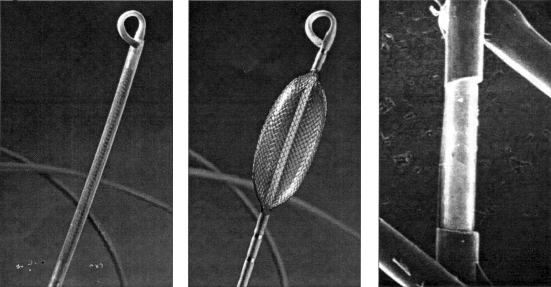
The non-contact mapping catheter with 9 French shaft (left), deployed 7.5 ml balloon with braided microelectrode array (centre), and micrograph of 0.025 inch long electrode created by removing a spot of insulation with a laser (right).
The MEA catheter consists of a 7.5 ml balloon mounted on a 9 French catheter around which is woven a braid of 64 insulated 0.003 inch diameter wires, each with a laser etched break in insulation, producing 64 non-contact unipolar electrodes. An electrically based locator signal is also generated by the system and simultaneously sensed by the MEA to track the position of a standard roving contact catheter. The system is applied in three steps: (1) establish chamber geometry; (2) identify site(s) critical for maintenance of re-entry circuit(s); (3) navigate ablation catheter to critical site(s).
Locator system
The system locates any conventional catheter with respect to the MEA by using a custom algorithm to locate the position of a 5.68 kHz, low current “locator” signal emitted from any of the catheter electrodes. This locator system serves two purposes.
First, it can be used to construct the three dimensional computer model of the endocardium (virtual endocardium) which is required for the reconstruction of endocardial electrograms and isopotential maps (fig2). This model is acquired by moving a conventional catheter around the cardiac chamber, building up a series of coordinates for the endocardium, and generating a patient specific, anatomically contoured model of its geometry. The chamber coordinates are sampled at the beginning of the study during sinus rhythm and are taken by gating each sample 6 ms after the peak of the R wave. The total time required to define the contoured geometry is typically between 5–10 minutes.

A contoured model of the chamber geometry is created by tracing the endocardial surface with a conventional roving catheter while the system tracks its position. The geometry is partially defined midway through the process in the left panel, completed and smoothed in the centre panel, and rendered in the right panel as an anatomically-contoured, wire-frame three dimensional model.
Second, the locator signal can be used to display and log the position of any catheter on the virtual endocardium and can be used to guide the catheter to sites of interest identified on the isopotential colour maps.
Inverse solution reconstruction of endocardial potentials
The electrical activity detected by the electrodes on the surface of the MEA is generated by the potential field on the endocardial surface. Cavitary electrograms detected by non-contact electrodes are of lower amplitude and frequency than the source potentials on the endocardium.15 ,16 ,21 A technique to enhance and resolve the actual endocardial surface potentials has been devised based on an inverse solution to Laplace’s equation using a boundary element method.
Using these techniques, the system is able to reconstruct and interpolate > 3000 unipolar electrograms simultaneously over the entire virtual endocardium (fig 3). These electrograms may be superimposed on the virtual endocardium to produce isopotential or isochronal maps with a colour range representing voltage or timing of onset. In addition, the electrograms may be interactively selected with the mouse pointer from anywhere on the virtual endocardium and displayed as waveforms.

Timing difference between conventional contact electrograms and non-contact reconstructed electrograms recorded during sinus rhythm. A mean timing difference of −0.9 ms and a mean morphology cross correlation of 0.83 was demonstrated over a population of 31 487 recorded cardiac cycles. One half of the time differences were within 2 ms and 77% were within 10 ms.
Initial clinical experience with ventricular tachycardia
Twenty four patients have undergone left ventricular mapping and ablation of well tolerated ventricular tachycardia at our centre. The patients’ mean age was 58 years (range 19–76 years) and two were female. Nineteen patients had sustained one or more myocardial infarctions, six patients had discrete aneurysms, and eight patients had undergone previous coronary artery bypass surgery. At the time of the procedure 21 patients were on amiodarone treatment and four of these patients were on an additional antiarrhythmic agent. Eight patients had implantable defibrillators of whom four requested an ablation procedure after frequent tachycardias and therapies; the other four had experienced slow ventricular tachycardia which prevented programming of the detection criteria without risk of inappropriate device treatments. Twenty patients had ischaemic heart disease, two patients had a dilated cardiomyopathy, one patient had fascicular tachycardia, and one patient had left ventricular ectopic tachycardia. Patients were excluded from the study if there was a contraindication for left ventricular mapping, specifically the presence of left ventricular thrombus, notable aortic valve disease, or contraindications for anticoagulation. Transoesophageal echocardiography was also performed before the procedure to exclude thrombus and notable aortic atheroma.
Mapping protocol
Two deflectable 7 French 4 mm tip mapping and ablation catheters were passed to the LV by transaortic and transeptal routes (fig 4). Pulmonary and systemic arterial pressures were monitored and activated clotting time maintained between 300 and 400 seconds to prevent thrombus formation on the MEA. Contact electrograms and surface ECGs were recorded simultaneously on conventional and non-contact electrophysiology systems.

A posterio-anterior radiograph showing the non-contact mapping catheter with 7.5 ml of contrast medium/saline in the balloon, deployed in the left ventricle(A). Also seen in the left ventricle is a transeptal mapping catheter (B) and a retrograde transaortic mapping catheter (C). Other catheters are positioned in the right ventricular apex and coronary sinus. This patient also has an implantable defibrillator lead (D).
The system was used to guide a conventional catheter to a site of interest identified on the virtual endocardium after less than 10 minutes of online review of isopotential maps produced from recordings of VT morphology. Diastolic pathways were identified on the unipolar isopotential maps and the locator system was then used to guide the catheter to points on these diastolic pathways. If conventional mapping techniques confirmed the validity of these sites then the site was logged on the virtual endocardium and radiofrequency energy delivered.
Initial experience indicated that diastolic depolarisation could, at times, be confused with repolarisation. In order to avoid this problem, strict criteria were defined for identifying diastolic depolarisation and all other diastolic signals were rejected as possible noise or repolarisation. Identification of diastolic pathways was started by identification of the VT exit site which was defined as a rapidly spreading focus of activity coincident with onset of the QRS complex on the surface ECG, leading to systolic activation of the ventricle. Diastolic activity during VT was then defined as activity progressing in a continuous fashion to the VT exit site. In practice the exit site can be seen as a white spot of activation when an isopotential map is displayed at the onset of surface ECG QRS complex. Diastolic activity is then identified by moving the isopotential map display back in time. When a discrete spot of diastolic activity can no longer be seen on the map then the limit of the diastolic pathway identified by the system has been reached and in accordance to the definition used all diastolic activity identified before this is ignored.
For the radiofrequency applications made during VT, successful ablation of a particular morphology of VT was defined as termination of VT during radiofrequency application with subsequent failure to induce the same morphology of tachycardia and with no recurrence within one month.
Results
Eighty one induced morphologies of VT were mapped using the non-contact system (mean of 3.4 per patient) (fig 5). Sixteen other morphologies were induced by catheter manipulation before introduction of the MEA, and thus were not included in the statistical analysis. Twenty four of the mapped VTs (30%) were clinical morphologies of ventricular tachycardia, with “clinical” defined as morphologies that had been documented to have occurred outside the setting of ventricular stimulation. The exit site demonstrated by the non-contact system was confirmed in 80 morphologies (99%) by comparison with the time of local activation at adjacent sites as well as with the time of earliest onset of the QRS complex of the surface ECG.
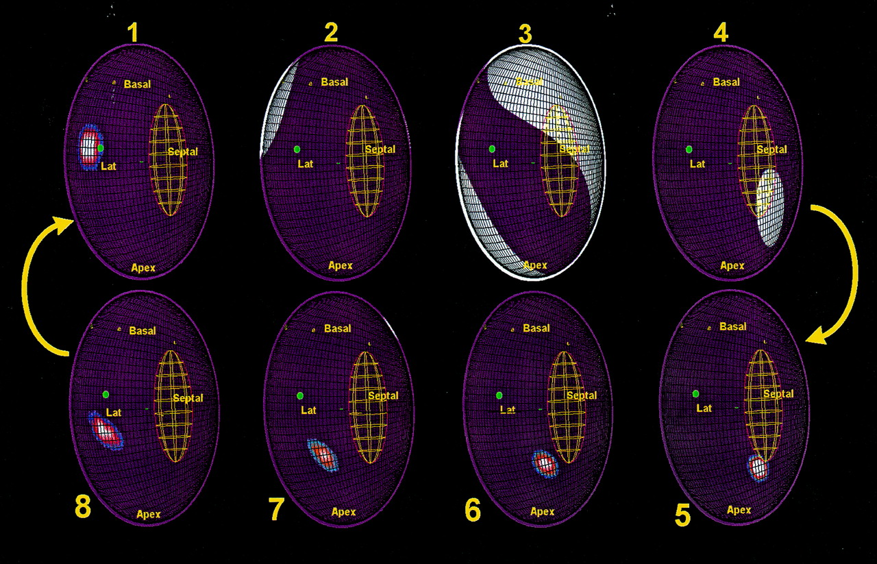
Activation maps recorded during VT in a patient with two VT morphologies using the same re-entry circuit in contrarotation. The virtual endocardium has been opened along the anterior septum so that the two edges are in continuity. Labels have been placed on sites identified using fluoroscopy as follows: Basal, left ventricle base; Apex, left ventricle apex; Septal, septum; Lat, lateral. Activation is indicated by white areas. The successful radiofrequency site is shown with a green dot. Activation reaches the exit of the diastolic component of the re-entry circuit (frame 1) before systolic activation of the left ventricle is seen (frames 2 to 4); note the sparing of the region of the diastolic pathway. The lines of conduction block that define this diastolic pathway are shown as green lines. The wavefront re-enters the diastolic pathway (frames 5 to 8) and progresses from the apicoseptum to exit at the basal-lateral end (frame 1).
Activity in some or all of the diastolic interval was thus identified in 54 VT morphologies (67%). In 17 of these (21%), the non-contact mapping system appeared to demonstrate a complete tachycardia circuit. In the remaining 37 circuits (46%), diastolic activity was traced over 36 (30%) of the diastolic interval (range 1 to 95%).
Radiofrequency energy was applied 154 times to ablate successfully 37 VTs (mean of 4 applications per morphology). Fourteen clinical (38%) and 23 non-clinical (62%) morphologies of VT were ablated. Of the seven morphologies of VT ablated, in which the entire circuit was defined, the site of successful radiofrequency application was within the diastolic pathway identified by the non-contact system in all cases. Interestingly, ablation was achieved with two applications of radiofrequency energy on common shared diastolic pathways in four of these (table 1).
Results of radiofrequency application during VT
Fourteen (58%) patients have been arrhythmia free over the 1.5 year follow up period. Only 2 (5.4%) of the 37 target VTs have recurred, both of which were subsequently successfully ablated using conventional techniques guided by non-contact data from the previous procedure. In the six patients in whom interrogation of an implantable defibrillator was possible both before and after the procedure, treatments have been significantly reduced following the ablation procedure from a mean of 9.2 shocks per year to 0.16 shocks per year (only one shock in one patient) (p < 0.05).
Complications
No patient suffered a cardiac complication as a result of deployment of the non-contact mapping system. Two of the first patients studied, who both had diffuse vascular disease, developed false aneurysms of the femoral artery which required surgical repair. In one patient this was at the site of introduction of the MEA. Following these cases, the protocol for removal of arterial sheaths was changed so that protamine was given to reverse anticoagulation and the sheaths were removed immediately after completion of the study and there have been no further vascular complications. Four other patients had procedural complications unrelated to use of the MEA, all of whom made a complete recovery. There have been no confirmed MEA catheter related deaths reported.
Discussion
Using non-contact data to guide the ablation, the success rate over a follow up period of 1.5 years has been greater than 78% in those patients who survived the perioperative period. The non-contact mapping system described here has several potential advantages over conventional and alternative methods because high resolution maps of the entire cardiac chamber are produced by simultaneous computation of endocardial electrograms, resulting in a complete map from even one beat of tachycardia. In addition, an anatomically relevant representation of the cavity geometry is obtained with a limited need for an alternative imaging system. Further still, the progress of a catheter within the cavity can be continuously tracked and recorded during mapping.
Validation has been performed in the human heart by comparing contact and reconstructed electrograms recorded from the same site on the endocardium, and these data demonstrate good correlation between contact and reconstructed electrograms. However the differences in contact and reconstructed electrograms increase with increasing distance between the MEA and the endocardium and this difference becomes significant when this distance is greater than 34 mm.22 ,23
There are several possible explanations for the non-contact system failing to identify a VT diastolic pathway completely. In some cases, the locations of the re-entry circuit were some distance from the MEA and this may have an effect on the accuracy of electrogram reconstruction. Nevertheless, in several of the cases where complete tachycardia circuits were apparently identified, the location was at least 40 mm from the MEA centre and beyond the present limit of the system’s optimal reconstruction. It is therefore difficult to define just how much of a role distance plays in errors of reconstruction of re-entry circuit electrograms. It may be that the volume of tissue forming the diastolic component of the re-entry circuit is insufficient to produce electrogram amplitudes that can be distinguished by the non-contact system. It is also possible that, in some of the cases, the diastolic component of the re-entry circuit that was not identified was intramural or epicardial and, therefore, could not be detected by the system. Another difficulty with identifying diastolic components of re-entry circuits is the saturation of the isopotential maps by repolarisation of the bulk of the ventricle. This problem is emphasised with non-contact mapping because the electrograms produced may be of lower frequency and amplitude than the equivalent contact electrogram and thus similar to repolarisation.
The low incidence of recurrence of VT in this series is impressive when one considers that some 43 tachycardias induced during the procedures were either not targeted or not ablated successfully, according to the end points of success at the time of study. It is possible that the particular morphology that had caused previous symptoms was eliminated in the majority of cases and that other morphologies induced were irrelevant to the clinical situation. In many cases, VT was difficult to sustain during a study; therefore applications were made during sinus rhythm rendering the VT non-inducible, even though no clear evidence of successful ablation of VT had been obtained. It may also be possible that the process of delivering radiofrequency energy in the region of re-entry circuits alters other local substrates predisposing to re-entry and thus reduces the frequency of VT without eliminating the circuits themselves. A further explanation for the low recurrence rate may be that several VT morphologies were using similar re-entrant circuits with different exits and that a single radiofrequency application eliminated more than one VT. There is some evidence for this in that the maps showed different VT morphologies using the same diastolic component of the re-entry circuit, either in contrarotation or with different exits, in at least four cases. In other cases where complete circuits could not be identified, it was apparent that the exit sites of several morphologies of VT were in close proximity.
Conclusion
This non-contact mapping system has been safely used to map ventricular tachycardia in the human left ventricle and has been associated with a low VT recurrence rate (5.4%) and a significant reduction in implantable defibrillator therapies (from 9.2 to 0.16 shocks per year). It has rapidly identified tachycardia exit sites and thus at least provided a potential starting point for conventional mapping. However, in over 50% of cases the system was also able to identify online at least some of the diastolic component of the re-entry circuit and therefore a suitable target for ablation. It has also proved to be a useful method for tracking the position of catheters and deliveries of radiofrequency energy. In some cases where a complete circuit could be identified, the data provided by the non-contact system could be validated by the location of the successful ablation site. The data presented here are on a selected group of patients, most of whom had haemodynamically stable VT; it remains to be shown whether such a system could be applied to unstable VT.
Acknowledgments
This paper is based on the winning presentation for the Young Research Worker’s Award at the British Cardiac Society meeting in Glasgow in May 1998.