Article Text

Abstract
Aims Different two-dimensional (2D) and three-dimensional (3D) imaging techniques are used for procedure planning and selection of prosthesis size before transcatheter aortic valve implantation. This study sought to compare different 2D and 3D imaging techniques and determine the accuracy of 3D transoesophageal echocardiography (TEE) for accurate analysis of aortic annulus dimensions.
Methods In 49 consecutive patients with severe aortic stenosis undergoing transcatheter aortic valve implantation angiography, 2D transthoracic echocardiography (TTE), 2D and 3D TEE, and dual-source CT (DSCT) were performed to determine aortic annulus diameters. TTE and 2D TEE provided only one diameter of the aortic annulus. Angiography, DSCT and 3D TEE allowed measurement of diameters in sagittal and coronal views. The distance between aortic annulus and left main coronary artery ostium was measured by angiography, DSCT and 3D TEE.
Results Sagittal diameters determined by angiography, TTE, 2D TEE, 3D TEE and DSCT were smaller than coronal diameters determined by angiography, 3D TEE and DSCT. Coronal and sagittal diameters determined by 3D TEE were in high agreement with corresponding measurements by DSCT (23.60±1.89 vs 23.46±2.07 mm and 22.19±1.96 vs 22.27±2.01 mm, respectively; mean±SD). There was a high correlation between DSCT and 3D TEE for the definition of coronal and sagittal aortic annulus diameters (r=0.88, SEE=0.89 mm and r=0.77, SEE=1.26 mm, respectively). Correlation of 3D TEE (13.47±1.67 mm) and DSCT (13.64±1.82 mm) in the analysis of the distance between aortic annulus and left main coronary artery ostium was better (r=0.54, SEE=1.55 mm) than between angiography (14.85±3.84 mm) and DSCT (r=0.35, SEE=1.77 mm).
Conclusions 3D imaging techniques should be used to evaluate aortic annulus diameters, as 2D imaging techniques, providing only a sagittal view, underestimate them. 3D TEE provides measurements of aortic annulus diameters similar to those obtained by DSCT.
- Aortic stenosis
- CT
- echocardiography
- transcatheter aortic valve implantation
- CT scanning
- echocardiography (three-dimensional)
- percutaneous valve therapy
- aortic valve disease
Statistics from Altmetric.com
- Aortic stenosis
- CT
- echocardiography
- transcatheter aortic valve implantation
- CT scanning
- echocardiography (three-dimensional)
- percutaneous valve therapy
- aortic valve disease
Introduction
Transcatheter aortic valve implantation (TAVI) has evolved into an alternative to surgical aortic valve replacement for severe aortic stenosis in patients with high surgical risk or contraindication to surgery.1–6 Paravalvular aortic regurgitation can be observed in at least 50% of patients, being one of the most common limitations.7 To minimise paravalvular aortic regurgitation, appropriate annular measurements and prosthesis sizing are critical. Two-dimensional (2D) echocardiography has been the most commonly used imaging modality for this purpose.8 Three-dimensional (3D) imaging using CT or MRI has demonstrated an ellipsoid geometry of the aortic valve annulus.9–11 Thus any 2D imaging technique allowing analysis of the annulus diameter in just one view is at risk of underestimating the maximal valve annulus diameter. To adjust for this, CT has recently been suggested for improved preprocedural annular measurement and prosthesis sizing.12–15 3D transoesophageal echocardiography (TEE) allows analysis of cardiac structures in any view similar to CT.
This study aimed to evaluate (1) potential differences in annular dimensions determined by 2D imaging techniques compared with 3D imaging techniques and (2) whether 3D TEE measurements of annular dimensions allow more accurate analysis of annular diameters than 2D TEE using dual-source CT (DSCT) as reference.
Methods
Patients
The study population consisted of 49 consecutive patients (mean±SD age 81.7±7.4 years, 16 male) with severe aortic stenosis undergoing TAVI. In all patients, angiography, 2D transthoracic echocardiography (TTE) and 2D TEE were performed as 2D imaging techniques, and DSCT and 3D TEE were performed as 3D imaging techniques. Diameters of the aortic annulus, the distance between the aortic root and left main coronary artery ostium, and the distance between the aortic root and right coronary artery ostium were determined. The position of the annulus diameter measurement relative to the aortic annulus circumference for each of the five evaluated methods is shown in figure 1.

Models of the aortic arch showing for each applied imaging modality the cut planes of the aortic annulus. (A) Angiography in 90° left anterior oblique (LAO) projection with an orange arrow indicating the sagittal annulus diameter (left) and 0° posteroanterior (p.a.) projection with a blue arrow indicating the coronal annulus diameter (right). (B) Transthoracic echocardiography (TTE) (left) and two-dimensional (2D) transoesophageal echocardiography (TEE) (right) left ventricular outflow tract (LVOT) view of the aortic annulus. The cut planes slightly differ because parasternal and mid-oesophageal acoustic windows do not exactly oppose to each other. Both TTE and 2D TEE LVOT view resemble a sagittal view (bright and dark yellow arrows, respectively). The direction of the arrows in the aortic arch model and the echo images indicate the scanning direction. Individual adjustments in scan plane direction are shown in the model. (C) Three-dimensional (3D) TEE cropped images of a sagittal (left) and coronal (right) view with the corresponding diameters (orange and blue arrows). The sagittal and coronal cut planes are depicted in the aortic arch model and the anatomic short-axis view (middle). (D) Dual-source CT (DSCT) reconstructed images of a sagittal (left) and coronal (right) view with the corresponding diameters (orange and blue arrows). The sagittal and coronal cut planes are depicted in the aortic arch model and the anatomic short-axis view (middle). Ao, ascending aorta; LA, left atrium.
For each modality, image acquisition and analysis were performed by physicians who specialise in the technique. The study was approved by the local ethics committee, and each patient gave written informed consent.
Angiography
Angiography was performed with injection of 25 ml of the contrast agent, iopromide 370 (Ultravist 370; Bayer-Schering Pharma AG, Berlin, Germany), at a rate of 14 ml/s into the aortic bulbus in 0° posteroanterior (PA) and 90° left anterior oblique (LAO) projections. A special pigtail marker catheter with 10 radio-opaque markers at 10 mm distances was used, allowing digital calibration. Subsequent measurements of aortic annulus coronal diameter and distance of aortic annulus to left main coronary artery origin were obtained edge-to-edge in the 0° PA projection. Corresponding measurements of the sagittal diameter of the aortic annulus and the distance of the aortic annulus to the right coronary artery origin were obtained edge-to-edge in the 90° LAO projection (figure 1A). The applied setting of the angiographic scanner resulted in a spatial resolution of ∼0.24 mm.
2D transthoracic echocardiography
Echocardiographic studies were performed with a commercially available echocardiographic system (Vivid 7; General Electric, Vingmed, Horton, Norway) and 2D transthoracic probe (M4S). Parasternal long-axis loops of the aortic root were acquired with zoom mode. Aortic annulus diameters were measured off-line with the aid of a dedicated software package (EchoPAC; General Electric) at the insertion of the leaflets in end diastole (figure 1B).
2D and 3D transoesophageal echocardiography
TEE was performed with a commercially available echocardiographic system (iE 33; Philips Medical Systems, Andover, Massachusetts, USA) and a TEE probe (X7-2t), allowing acquisition of 2D and 3D TEE images. This transducer uses approximately 3000 elements to acquire a pyramidal volume up to 102°×105°. Spatial and temporal resolution is dependent on depth and direction of measurements, with better spatial resolution in the axial than the lateral direction.
2D image acquisition and analysis
Left ventricular outflow tract views were acquired in mid-oesophageal position with scanning planes from 115° to 150° in order to show the largest extension of the aortic annulus in the centre of the aortic root with zoom mode. The annulus diameter was measured off-line with the aid of dedicated software (QLAB-Version 7.0; Philips Medical Systems) at the insertion of the leaflets in end diastole (figure 1B).
3D image acquisition and analysis
3D zoom mode was used to acquire loops with the narrowest possible depth and adjustment of lateral width and elevation width resulting in a volume containing the whole aortic root, the left ventricular outflow tract and the ascending aorta. 3D diameters were assessed off-line with the aid of a commercially available software package (3DQ, QLAB-Version 7.0; Philips Medical Systems). Standard short-axis views of the aortic valve were generated at the insertion of the leaflets in end diastole. A sagittal view was obtained by adjusting a cut plane in mid-position of the short-axis view along the ascending aorta, where measurement of the sagittal diameter of the aortic annulus was performed. A coronal view was obtained by adjusting a cut plane in mid-position of the short-axis view along the ascending aorta oblique to the sagittal plane. The coronal cut plane was adjusted until the left main coronary artery ostium appeared, where measurements of the coronal diameter of the aortic annulus and the distance between the annulus and the left main coronary artery ostium were performed (figure 1C).
Dual-source CT
All CT examinations were performed with a dual-source scanner (Definition; Siemens, Forchheim, Germany) as part of a complete aortic study using a standardised imaging protocol with prospective ECG triggering set to 70% of the RR cycle for unenhanced images and retrospective ECG gating for contrast-enhanced scans. This allowed definition of aortic valve calcification and evaluation of the vascular access site in addition to analysis of aortic valve annulus dimensions. The scan parameters for non-enhanced DSCT examination were as follows: 32×0.6 detector collimation with 64×0.6 mm image acquisition by use of a flying z-focus, tube voltage 120 kV, 80 mAsrot tube current; for contrast-enhanced imaging, the pitch was individually adapted to the patient's heart rate ranging from 0.25 to 0.48. A tube current-time product of 400 mAsrot plus tube current modulation (Care Dose 4D; Siemens) was used. ECG pulsing was performed, reducing tube current during systole to 4% of its nominal value.16 The ECG pulsing window was set to 65–75% in patients with a heart rate ≤70 beats/min and 40–75% of the RR interval if the heart rate exceeded 70 beats/min. The applied setting of the CT scanner resulted in a spatial resolution of ∼0.4 mm. For contrast enhancement, iopromide 370 was administered via an 18G access in the right cubital vein using a biphasic contrast injection protocol. First, 30 ml contrast medium was injected at an iodine-delivery rate of 4.9 ml/s, followed by 40 ml administered at an iodine-delivery rate of 4.1 ml/s. Contrast injection was followed by a saline chaser bolus at a flow rate of 4.1 ml/s.
The average heart rate of the patients was 69±6 beats/min. Unenhanced axial images were reconstructed with a slice thickness of 3 mm with an increment of 2 mm using a dedicated convolution kernel (B35f). Contrast-enhanced images were computed using a motion map algorithm (Cardio BestPhase, Siemens, Germany) during the diastolic phase with least motion, with an effective slice thickness of 0.75 mm and a reconstruction increment of 0.4 mm. The field of view was 180×180 mm2 with a 5122 matrix.
Image analysis was performed on a separate computer workstation (MMWP; Siemens). Standard orthogonal axial and sagittal views were used for orientation on the aortic valve. As the aortic valve is oriented obliquely to the standard axial view, a coronal and a single oblique sagittal view through the aortic valve was reconstructed using DSCT datasets. The diameter of the aortic annulus was determined in diastole in the reconstructed oblique sagittal view and the coronal view (figure 1D). To ensure correct orientation of both views, the reconstructed double oblique transverse view at the level of the aortic valve was reviewed. Moreover, the distance between the annulus and the left main coronary artery ostium was evaluated in the coronal view and the distance between annulus and right coronary artery ostium in the sagittal view.
Observer agreement
In 24 randomly selected studies, aortic annulus diameters were remeasured by the same observers at a separate time to determine intraobserver agreement and by another observer to determine interobserver agreement. Intra- and inter-observer agreement were evaluated for angiography, DSCT, TTE, 2D TEE and 3D TEE.
Statistical analysis
Statistical analysis was performed with the help of a statistical analysis program (MedCalc Software, Version 9.5.1.0). Continuous data are presented as mean±SD, and categorical data as frequencies. Paired-samples t test and one-way analysis of variance were performed. Pearson correlation coefficients (r) with p value and 95% CI for r were calculated. Intraobserver and interobserver correlation and SE of estimate (SEE) by linear regression analysis were determined for angiography, DSCT, TTE, 2D and 3D TEE. Measurements determined by DSCT were compared with those obtained by angiography, TTE, 2D and 3D TEE using linear regression and Bland–Altman analysis. p<0.05 was considered significant.
Results
Clinical baseline characteristics of the 49 study patients are given in table 1. All patients had severe aortic stenosis: the mean aortic valve area was 0.64±0.19 cm2 and mean gradient was 45.9±16.5 mm Hg. The logistic Euroscore of the patients was 26±13%.
Characteristics of the 49 patients in the study
Aortic annulus diameters
Table 2 shows measurements of the aortic annulus diameter obtained by the different imaging modalities. Diameter measurements were found to be smaller by angiography in 90° LAO projection, TTE, 2D TEE, sagittal view analysis by DSCT and sagittal view analysis by 3D TEE compared with measurements obtained by angiography in 0° PA projection, coronal view analysis by DSCT, and coronal view analysis by 3D TEE.
Measurements of aortic annulus diameter derived from sagittal and coronal cut planes using different echocardiographic modalities, angiography and dual-source CT (DSCT)
There was moderate correlation between angiography in 90° LAO projection and sagittal view DSCT as well as between angiography in 0° PA projection and coronal view DSCT in the measurement of the aortic annulus diameter (r=0.74, SEE=1.35 mm and r=0.56, SEE=1.60 mm, respectively).
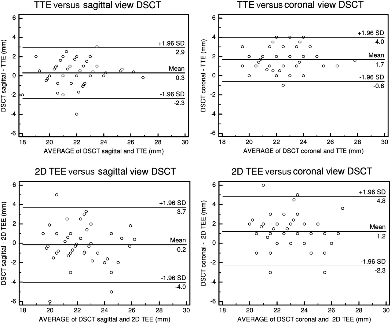
There was a similar correlation between aortic annulus diameter measurements by 2D TTE and sagittal view DSCT (r=0.76, SEE=1.31 mm). There was a smaller difference between aortic annulus diameter measurements by TTE and sagittal view by DSCT (average bias 0.3 mm, 95% CI −2.3 to 2.9 mm) than between measurements by 2D TTE and coronal view DSCT (average bias 1.7 mm, 95% CI −0.6 to 4.0 mm) (p=0.001). Similarly, agreement between aortic annulus diameter determined by 2D TEE and sagittal view DSCT (average bias −0.2 mm, 95% CI −4.0 to 3.7 mm) was better than agreement of diameters determined by 2D TEE and coronal view DSCT (average bias 1.2 mm, 95% CI −2.3 to 4.8 mm) (p<0.001) (figure 2).

Bland–Altman plots demonstrating agreement of aortic annulus diameters determined by transthoracic echocardiography (TTE) to sagittal and coronal diameters by dual-source CT (DSCT) (upper left and right panels). Bland–Altman plots demonstrating agreement of two-dimensional (2D) transoesophageal echocardiography (TEE) to sagittal and coronal diameters by DSCT (lower left and right panels).
There was a high correlation between DSCT and 3D TEE in the definition of the sagittal diameter (r=0.77, SEE=1.26 mm) and the coronal diameter (r=0.88, SEE=0.89 mm) of the aortic annulus. There was only a small difference between DSCT and 3D TEE in the definition of sagittal annulus diameter (average bias −0.1 mm, 95% CI −2.7 to 2.6 mm) as well as coronal aortic annulus diameter (average bias 0.1 mm, 95% CI −1.8 to 2.0 mm) (figure 3).

Linear regression plots (upper panels) and Bland–Altman plots (lower panels) demonstrating the agreement of dual-source CT (DSCT) and real-time three-dimensional (3D) transoesophageal echocardiography (TEE) in the analysis of sagittal annulus diameters (left panels) and coronal annulus diameters (right panels).
Distance between aortic annulus and origin of the coronary arteries
Table 3 shows measurements of the distance between the aortic annulus and the left main ostium, as well as the right coronary artery ostium, determined by angiography and DSCT. In addition, table 3 shows measurements of the distance between the aortic annulus and the left main ostium determined by 3D TEE. Measurements obtained by angiography were larger than those obtained by DSCT and by 3D TEE. Measurements of the distance between the aortic annulus and the left main coronary artery ostium obtained by 3D TEE were in greater agreement with those determined by DSCT (average bias 0.2 mm, 95% CI −3.1 to 3.5 mm) than were measurements obtained by angiography (average bias to DSCT −1.2 mm, 95% CI −8.3 to 5.9 mm) (figure 4).
Measurements of the distance between left main coronary artery and aortic annulus as well as right coronary artery and aortic annulus using angiography, dual-source CT (DSCT) and three-dimensional transoesophageal echocardiography (3D TEE)

Bland–Altman plots demonstrating the agreement between measurement of the distance between left main coronary artery ostium (LM) and aortic annulus obtained by three-dimensional transoesophageal echocardiography (TEE) and dual-source CT (DSCT) (left panel) and between those obtained by angiography and DSCT (right panel).
Observer agreement
Intraobserver correlation of measurements of the aortic annulus diameter performed on sagittal and coronal DSCT views, on 3D TEE, 2D TTE and 2D TEE views was high. Similarly, the interobserver correlation of measurements performed on DSCT views, on 3D TEE, 2D TTE and 2D TEE views was high. In contrast, intraobserver and interobserver correlation of aortic annulus measurements on sagittal and coronal angiography views was only moderate (table 4).
Intraobserver and interobserver correlation coefficient (r) and SE of estimate (SEE) of measurements of the aortic annulus diameter by different imaging modalities
Discussion
This study confirms previous findings that the aortic annulus has an oval shape and that 2D imaging techniques may result in underestimation of aortic annulus diameters. The major new findings are that (1) 3D TEE provides aortic root dimensions similar to those obtained by DSCT, and (2) intraobserver and interobserver correlation in the measurement of aortic annulus diameters is high using DSCT as well as echocardiographic techniques, but less with angiography.
Sizing of the aortic annulus
Adequate sizing of the prosthesis is of critical importance for TAVI. Performance of several measurements of the aortic valve and root is recommended when planning a TAVI procedure. Measurement of the aortic annulus diameter is the most important for adequate sizing of the prosthesis. Definition of the distance between aortic annulus and coronary ostia is also recommended to prevent ostial coronary occlusion, in particular of the left main coronary. 2D TEE is the recommended and most commonly used technique for analysis of the aortic annulus diameter.4 8 17 Application of this technique for diameter measurement has assumed the aortic valve annulus to be circular, but recent studies using DSCT or MRI for 3D imaging have revealed an ellipsoid geometry.9–11 18 DSCT-derived diameters have been found to be larger than those derived by 2D TTE or TEE.12 Use of DSCT has therefore been recommended recently for improved sizing of the prosthesis to prevent mismatch between the self- or balloon-expandable prosthesis and the native aortic valve annulus.13 The absolute differences between the sagittal and coronal aortic annulus diameters determined in this study are small. However, these seemingly small differences may result in a different choice between the currently available two valve size prostheses. If borderline aortic annulus diameters related to the currently available prosthesis diameters are obtained, small differences in diameter measurements may even result in a different evaluation of the feasibility of performing TAVI.
Paravalvular aortic regurgitation, although minor in the majority of cases, occurs in at least 50% of patients, and the clinical significance is not clear.7 However, post-procedural paravalvular aortic regurgitation ≥2+ mainly affects late outcomes.19 20 Although initial reports have reported deep seating of the valvular prosthesis within the aortic annulus to be a determinant of paravalvular aortic regurgitation, more recent studies have indicated undersizing of the prosthesis to be an important determinant. Delgado et al reported larger annulus diameters in patients with more pronounced aortic regurgitation than in those without aortic regurgitation.13 Detaint et al reported the absence of severe aortic regurgitation if the prosthesis was slightly oversized as compared with annulus measurements performed by 2D TEE.21 Thus accurate annular measurements and prosthesis sizing are critical for minimising paravalvular aortic regurgitation.
2D versus 3D imaging techniques
The ellipsoid shape of the aortic annulus results in a larger diameter in the coronal direction and a smaller diameter in the sagittal direction. This study has evaluated for the first time in systematic fashion the ability of different 2D and 3D imaging modalities provided by angiography, echocardiography and CT to evaluate aortic annulus diameters. Measurement of aortic annulus diameter by 2D TTE and TEE could be performed with high intraobserver and interobserver agreement. Both techniques resulted in measurement of a diameter that is morphologically similar to the sagittal diameter measured by DSCT. TTE and 2D TEE provided similar results on the aortic annulus diameter. This is in agreement with a recent report by Messika-Zeitoun et al,12 but in disagreement with a study by Moos et al which demonstrated larger diameters measured by TEE than TTE.17 This may be explained by cut planes of the aortic annulus from transthoracic parasternal and mid-oesophageal acoustic windows that do not necessarily exactly oppose each other (figure 1B). Diameter measurements were very similar to those obtained by DSCT using the sagittal view. Thus diameters defined by TTE and 2D TEE were too small compared with the larger diameter obtained in the coronal direction by DSCT. This result is in agreement with previous reports demonstrating underestimation of annulus diameters by 2D echocardiographic techniques.13 Callipered angiography allowed the analysis of annulus diameters in the sagittal and coronal direction. Measured annulus diameters were similar to those obtained by DSCT, but correlation of measurements between angiography and DSCT was only moderate. Significant differences in annulus diameters have been reported between angiography and multidetector CT using right anterior oblique projections, but less significant differences were noted on LAO projections in a study on 40 patients.
3D TEE has been proposed for measurement of annulus dimensions, as it gives direct access to diameters without the need for assumptions on the circularity of the annulus.8 In a previous report by Ng et al, even 3D TEE was found to underestimate aortic annular area by ∼10%.14 In other reports, 3D echocardiography has been found to allow very accurate analysis of left ventricular dimensions.22 In this study, 3D TEE allowed accurate analysis of aortic valve diameters in the coronal and sagittal direction, with only minimal differences from measurements obtained by DSCT. Measurements of the coronal diameters were significantly larger than measurements obtained by 2D TTE and 2D TEE. It should be noted that image acquisition and analysis using 3D TEE requires special skills to obtain reliable data. In this respect, 3D TEE may be more operator dependent than DSCT.
Angiography is likely to be the least accurate technique for defining aortic annulus diameters, as it is a 2D imaging technique with projections that may not adequately reflect the largest diameter and potentially largest calibration difficulties before measurement of annulus size. Furthermore, aortic bulbus distortion, severe aortic calcification and insufficient contrast enhancement may impair accurate measurements of the aortic annulus diameter using angiography. Rotational angiography, which has recently become available, may enable improvements in the angiographic assessment of aortic annulus diameters.
Limitations
Owing to variability of the position of the heart within the chest, the acoustic windows of 2D TTE and 2D TEE provide variable views of the aortic annulus, which may deviate from the sagittal view obtained by DSCT. Thus coronal and sagittal imaging views of the different techniques may correspond grossly but not necessarily exactly. Similarly to TTE and 2D TEE, there are potential limitations in image quality using 3D TEE, in particular in patients with pronounced calcification, which may limit the accuracy of annular measurements. Annulus diameters, as well as distances between annulus and coronary ostia, were relatively small in this study compared with previous reports.10 13 This is probably due to a predominance of female patients in this study group. Annulus area-derived mean diameters were not calculated and included in the analysis to maintain homogeneity of analysis between 2D and 3D imaging techniques. We felt this to be adequate, as annulus area-derived mean diameters are not commonly used in clinical practice. The annular diameters obtained in the sagittal and coronal views may be slightly different from when imaging planes are obtained on 3D datasets using dedicated reconstruction software searching for minimal and maximal diameters. However, for practical reasons the use of sagittal and coronal planes has been the preferred approach in most recent studies.10 13 The 0° PA and 90° LAO projections used for angiography do not always provide perpendicular views of the aortic annulus, as has been shown by Kurra et al.23 This may lead to imprecise measurements of the aortic annulus diameters. However, individualised definition of angiographic views perpendicular to the aortic annulus may require acquisition of multiple views and is therefore not used in clinical practice.
Conclusions
3D imaging techniques should be used to evaluate aortic annulus diameters, as 2D imaging techniques providing only a sagittal view underestimate aortic annulus diameters.
3D TEE allows analysis of aortic annulus diameters similarly to DSCT. It may be used as a substitute for DSCT for the important job of prosthesis sizing before TAVI.
References
Footnotes
Competing interests None.
Patient consent Obtained.
Ethics approval This study was conducted with the approval of the University of Aachen.
Provenance and peer review Not commissioned; externally peer reviewed.