Article Text

Abstract
BACKGROUND Optical coherence tomography (OCT) is a new method of catheter based micron scale imaging. OCT is analogous to ultrasound, measuring the intensity of backreflected infrared light rather than sound waves.
OBJECTIVE To demonstrate the ability of OCT to perform high resolution imaging of arterial tissue in vivo.
METHODS OCT imaging of the abdominal aorta of New Zealand white rabbits was performed using a 2.9 F OCT imaging catheter. Using an ultrashort pulse laser as a light source for imaging, an axial resolution of 10 μm was achieved.
RESULTS Imaging was performed at 4 frames/second and data were saved in either super VHS or digital format. Saline injections were required during imaging because of the signal attenuation caused by blood. Microstructure was sharply defined within the arterial wall and correlated with histology. Some motion artefacts were noted at 4 frames/second.
CONCLUSIONS In vivo imaging of the rabbit aorta was demonstrated at a source resolution of 10 μm, but required the displacement of blood with saline. The high resolution of OCT allows imaging to be performed near the resolution of histopathology, offering the potential to have an impact both on the identification of high risk plaques and the guidance of interventional procedures.
- imaging
- intravascular ultrasound
- plaque rupture
- optical coherence tomography
Statistics from Altmetric.com
A need exists in at least two areas of cardiology for an imaging technology capable of defining arterial structure on a micron scale. These areas are the identification of high risk coronary plaques and the guidance of interventional procedures (for example, provisional stenting). The rupture of small, thin walled, lipid filled plaques in the coronary arteries has now been established as a critical mechanism, resulting in acute coronary syndromes.1 ,2 Current imaging technologies cannot reliably identify these lesions before rupture, predominantly because of limitations in resolution.3 Similarly, high resolution, real time imaging of plaque microstructure will likely also be beneficial in guiding coronary interventional procedures, such as directional and rotational atherectomy.4 Although these catheter based interventions are microsurgical procedures, removing tissue of only a few millimetres in depth, they are primarily guided by fluoroscopy, which has a resolution in the range of 500 μm during cardiac motion.5 Intravascular high frequency ultrasound (IVUS), the current clinical technology with the highest resolution (approximately 100 μm), has been applied to both the identification of high risk plaques and the guidance of interventional procedures.6 ,7 However, the reproducible identification of vulnerable lesions has not been achieved and its utility for guiding interventional procedures may be limited to stent placement.4 ,6 ,7
Optical coherence tomography (OCT) is a recently developed technology which generates images with micron scale resolution.8 OCT is analogous to ultrasound, measuring the intensity of backreflected infrared light rather than acoustical waves. An OCT image represents a cross sectional picture of the optical reflectance properties of tissue. Although the penetration of OCT is limited to 2–3 mm, the resolution of this technology, which is between 4 and 20 μm (depending on the source), represents an improvement of over 25 times that of high frequency ultrasound, magnetic resonance imaging, or computed tomography. OCT was originally developed to image the transparent tissue of the eye with unprecedented resolution.8 It has shown considerable promise for the diagnosis of a wide range of retinal-macular diseases.9 ,10
Recently, OCT imaging was extended to in vitro pathology in non-transparent tissue.11-13 This work includes multiple studies on atherosclerotic arteries.11 ,14 ,15 Structures characteristic of unstable plaque, such as thin intimal caps, focal lipid collections, and fissures have been identified in vitro at 16 μm resolution.11 Transluminal imaging completely through the normal coronary artery has been achieved.14OCT has also been directly compared with a 30 MHz IVUS transducer.15 ,16 In addition to qualitatively superior resolution with respect to imaging plaque, OCT was shown to be quantitatively superior with a mean (SD) axial resolution of 16 (1) μm for OCT compared with 109 (7) μm for IVUS.
A high speed catheter based OCT imaging system has been developed for intravascular imaging.17 The catheter is 2.9 F or 0.97 mm in diameter. It consists of relatively simple fibreoptics and, unlike ultrasound, contains no transducer within the catheter, making it relatively inexpensive. The axial resolution of this system is 10 μm with an acquisition rate of 4–8 frames/second. High resolution images of the in vivo rabbit oesophagus and trachea have recently been demonstrated with this system.17
This work represents the first demonstration of in vivo intravascular imaging with OCT. OCT imaging was performed within the aorta of a New Zealand white rabbit via a small, catheter based system. Particular attention was paid to assessing if blood interferes with the ability of OCT to assess the vessel wall, a clinically relevant question which has not been addressed previously.
Methods
In vivo imaging required several technical advances which have been described.17 First, a novel rapid data acquisition system allowed imaging at 4 frames/second, an increase in imaging speed of approximately two orders of magnitude from previous in vitro studies. This system uses a high speed scanning optical delay line, which is based on phase control techniques used in femtosecond pulse shaping.18 Second, the integration of a new high power, low coherence, short pulse solid state laser light source into the OCT system was required in order to achieve high detection sensitivities at high image acquisition rates.19 Third, a 2.9 F (0.97 mm), second generation OCT imaging catheter was developed for high speed transluminal imaging. These components were integrated into an in vivo imaging system which synchronised the catheter motor, frame grabber, and reference arm to a master clock. A schematic of the catheter OCT imaging system is shown in fig 1.
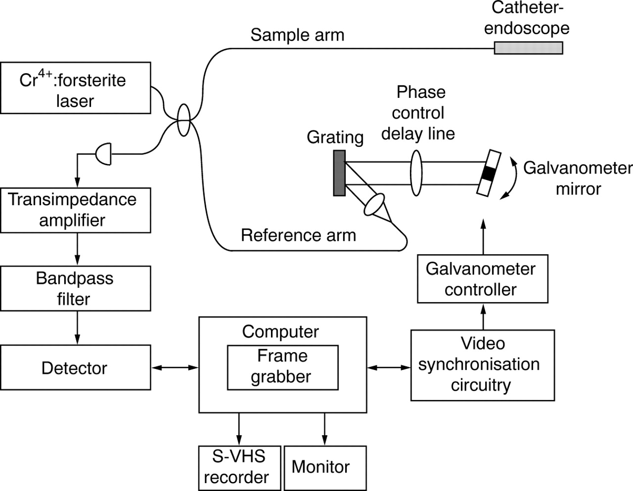
Schematic of OCT system. Laser source emits pulses that are split evenly, half toward the sample (through the catheter) and half toward the reference arm. If reflected light returning from the tissue and reference mirror arms arrives almost simultaneously, interference will occur. OCT measures the intensity of interference. The rotating mirror of the catheter, galvanometer, and frame grabber are synchronised with a master clock. Data are displayed on a monitor, and saved in either super VHS or digital format.
The principles behind OCT have been described previously.11 OCT measures the intensity of backreflected infrared light. The time for light to return to the detector, or echo delay time, is used to measure distances. In order to produce cross sectional tomographic images, the light beam is scanned across the tissue to produce two and three dimensional data sets. Because of the high speed of light propagation, a direct measurement of the echo delay time (time for reflected light to return) cannot be made electronically. To measure the delay time, OCT uses a technique known as low coherence interferometry, which compares the echo time delay of the light being measured to light which travels a reference path (a reference arm) of known length. In these experiments, the path length in the reference arm was scanned using a recently developed high speed optical phase control technique.17
A solid state laser, which generates pulses of femtosecond duration (∼10−15 s), was used for imaging. Specifically, a Kerr lens modelocked, Cr4+:Forsterite laser was used which had a median wavelength of 1280 nm and a bandwidth of 75 nm.19The bandwidth is essentially the width of the wavelength distribution of the beam. The bandwidth is inversely related to the coherence length (which determines the axial or longitudinal imaging resolution) via the formula: Δ = 2ln2 λ2/π Δλ
Therefore, the broader the wavelength distribution within the incident beam, the greater the resolution. The theoretical axial resolution of the system corresponding to the 75 nm bandwidth of the light source used is 10 μm.20 The axial resolution was confirmed experimentally by measuring the axial point spread function using a mirror, a standard technique for defining resolution. The axial pixel size was 9.2 μm. The transverse or lateral resolution is determined by the spot size or focusing power of the lens system and was measured to be 30 μm at 3 mm. The confocal parameter was 1.74 mm. Acquisition rates were 4 frames/second for an image consisting of 512 transverse pixels. The optical power incident on the sample was ∼10 mW. The signal to noise ratio was 106 dB.
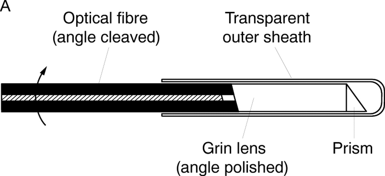
A schematic and photograph of the OCT imaging catheter is shown in fig2. The catheter consisted of an encased, rotating speedometer cable carrying a single mode optical fibre.17 The beam is focused by a graded index lens and is directed by a microprism. The beam was scanned circumferentially by rotating the cable, fibre, and optical assembly inside the static housing. Advantages of this catheter over the original prototype include the smaller diameter and the reduction of parasitic internal reflections, the latter being critical for high speed imaging. Power loss caused by suboptimal coupling and internal reflection within the catheter was 3–4 dB.


Schematic of transverse scanning catheter for high speed in vivo intra-arterial imaging. (A) The catheter consisted of an encased, rotating speedometer cable carrying a single mode optical fibre. The beam from the distal end of the fibre was focused by a gradient index (Grin) lens and directed perpendicular to the catheter axis by a microprism which performs circumferential imaging at 4 revolutions/second. (B) The catheter, which has an external diameter of 2.9 F or 0.97 mm.
The axial dimension (scan depth) of each OCT image was 2.3 mm which was digitised to 248 pixels. Imaging was performed with 512 transverse pixels (corresponding to different radial angles) with image acquisition times of 250 ms. Faster image acquisition times could be achieved by either reducing the number of axial scans or the scan depth. Data were recorded in both super VHS and digital format.
This protocol has been approved by the committee on animal care both at Massachusetts General Hospital and Massachusetts Institute of Technology. In vivo imaging was performed on two normal, 12 week old, New Zealand white rabbits. After the animals were anaesthetised, a mid-abdominal incision was performed and the viscera were retracted until the retroperitoneum was exposed. The abdominal aorta was isolated with blunt dissection. Umbilical sutures were placed around the proximal and distal portions of the aorta. The umbilical sutures were retracted until flow in the aorta had ceased. A nick was placed in the anterior surface of the aorta, just above the aortic bifurcation, using microscissors. A 7 F Judkins guiding catheter, with a Y connector on the proximal end, was introduced into the aorta using a microretractor. The guiding catheter was placed approximately 4 cm into the aorta directed from distal to proximal. The OCT imaging catheter was introduced through the centre of the guiding catheter. Imaging was performed over an approximately 8 cm length of aorta. When the influence of blood on imaging was assessed, normal saline was manually injected through the side port of the Y connector via a 50 ml syringe. After imaging, the animal was killed and the imaged regions were excised and immersed in 10% formalin in preparation for routine histological processing. Gross tissue registration was performed by suturing the guiding catheter in place after imaging. The specimens were blocked in paraffin, cut into 5 μm sections, and stained with haematoxylin and eosin for microscopic examination.
Axial resolution was confirmed in vivo semiquantitatively by measuring the point spread function off the luminal−intimal border and from fibres within the adventitia.20 Measurements of fibre widths within the adventitia were also compared between OCT and histology. Values represent mean (SEM) of five different sites from the same animal.
Results
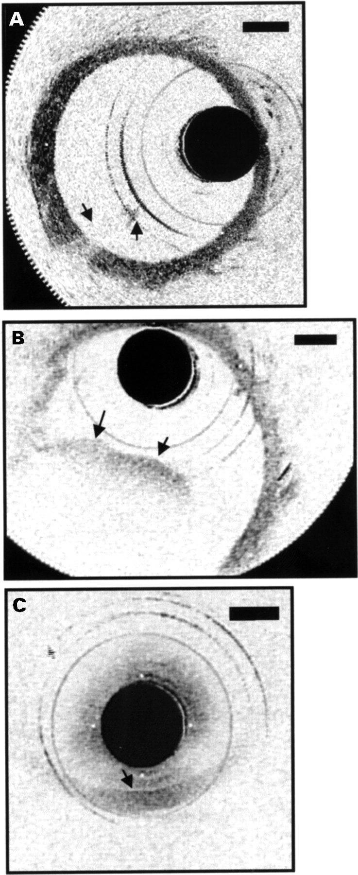
The influence of blood on OCT imaging, with and without saline injections, was demonstrated. The results of blood front moving in and out of the field of the image are shown in fig 3. Immediately following a saline injection, nearly the entire wall of the aorta was visible. A small portion of the front was present in the image, obstructing the view of the vessel wall behind it (fig 3A). The second image was taken when blood filled almost half the lumen, resulting in an inability to identify the vessel wall in this region (fig 3B). When no saline injection was performed, the wall could only be delineated when the catheter was in direct approximation (fig3C).

Movement of blood front in and out of field during saline injections. (A) A small portion of the front is present in the image (arrows), obstructing the view of the vessel wall behind it. (B) Blood now fills almost half the lumen (arrows), resulting in an inability to identify the vessel wall in this region. (C) No saline injection was performed. The wall could only be delineated when the catheter was in direct approximation (arrow).
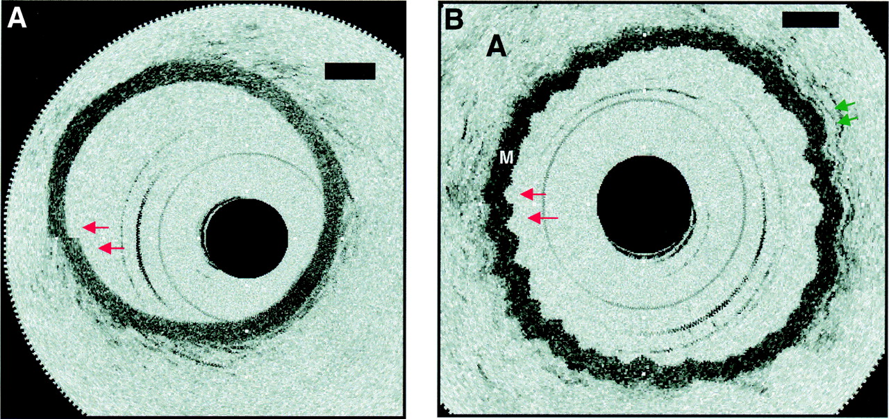
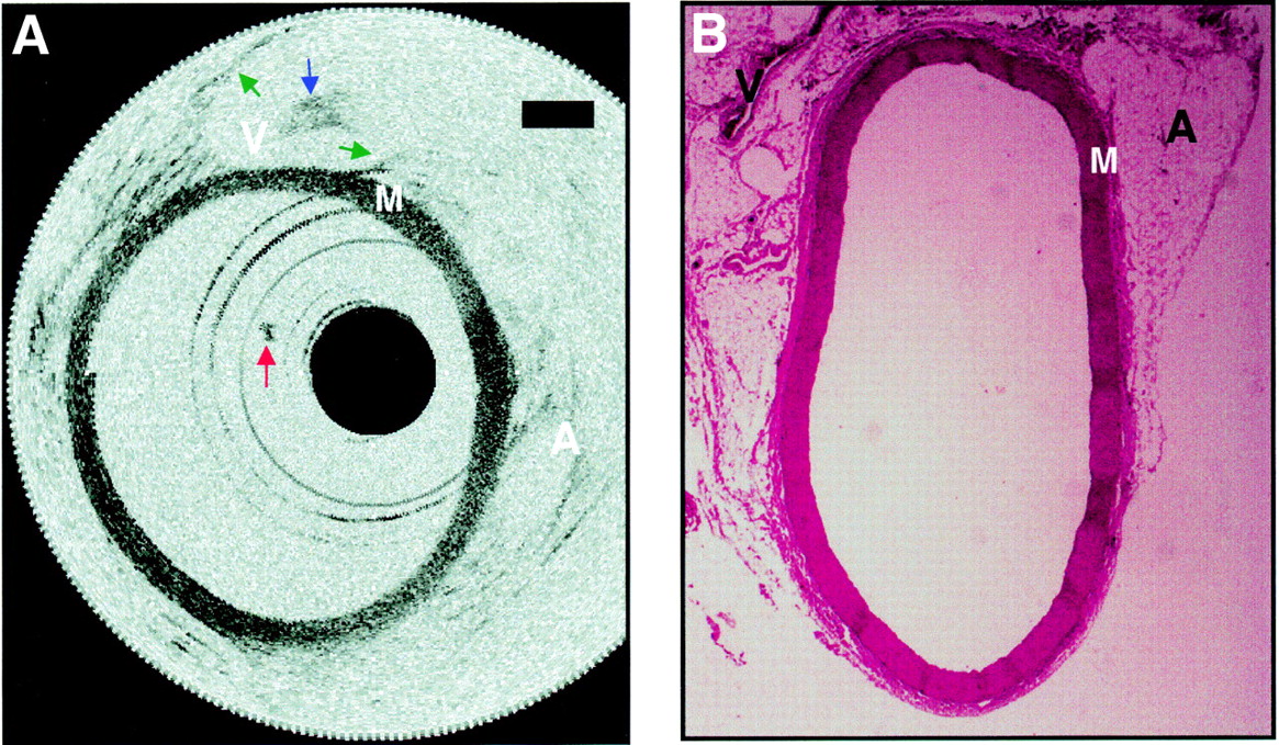
The aorta was imaged after a manual 2–3 ml/s saline flush (fig 4). In this image, the media and surrounding supportive structures were clearly identified. The intima, which is less than 10 μm in diameter, could not be detected in the images. Backscattering intensity was high in the media and low in the adventitia, which consisted primarily of loose connective tissue. A small clot adherent to the distal end of the catheter, which formed midway through imaging, was seen in many of the images. A structure consistent with the inferior vena cava was imaged through the wall of the aorta. Histology was included to confirm tissue identification. The aorta was imaged for over 45 minutes. In the presence of saline flushes, the entire aorta was visualised at all time. No significant difference was noted in image quality for vessel sizes ranging from 1.5–5 mm.

Aorta image after a saline flush and corresponding histology. (A) The media and surrounding supportive structures are clearly identified. The intima, which is less than 10 μm in diameter, cannot be detected in the images. Backscattering intensity is high in the media “M” and low in the adventitia “A”, which consists primarily of loose connective tissue. A small clot adherent to the distal end of the catheter, which formed midway through imaging, is seen in many of the images (red arrow). A structure consistent with the inferior vena cava “V” is imaged through the wall of the aorta. The walls of the inferior vena cava are noted (green arrows), as well as a blood clot within (blue arrow). Bars represent 500 μm in all images. (B) Histology has been included to confirm tissue identification.
Imaging was performed at 4 frames/second. It was shown that some motion artefacts do occur at this rate (fig 5). The vessel lumen appeared discontinuous since the rate of vessel wall movement exceeded the acquisition rate necessary to produce a 360o revolution (fig 5A). Imaging during rapid variations in saline flow produced a “wavy” appearance of the aorta. This was most likely a result of the rapid variation in flow as no blurring occurred in sections of the wall (fig 5B). Axial resolution was not influenced by motion artefacts because the measurement of backreflected light from different axial delays at each transverse position was performed very rapidly (within ∼0.5 ms, corresponding to 512 transverse pixels at 4 frames/second). Thus, the motion of the vessel wall during the measurement time was negligible.
Demonstration of motion artefacts while imaging at 4 frames/second. (A) The vessel lumen appears discontinuous (red arrows) since the rate of vessel wall movement exceeds the acquisition rate necessary to produce a 360o revolution. For accurate representations of luminal diameter, acquisition rates will need to be slightly higher. (B) This demonstrates imaging during rapid variations in saline flow. Even though a “wavy” appearance (green arrows) results from the rapid variation in flow, no blurring occurs in sections of the wall. Axial resolution is not influenced because the rate of image data acquisition in the axial direction is much faster than motion of the blood vessel. (“A”, adventitia; “M”, media.)
The point spread function at the luminal−intimal interface was measured at five different sites from the same animal to be 23 (5) μm (n = 5), while the point spread function in the adventitia (from loose connective tissue fibres) was 18.4 (1) μm (n = 5). These loose fibres were determined to be 13 (1) μm (n = 5) in width by histology, making the width measured by OCT of 18.4 (1) μm within the range of 1 pixel (9.2 μm).
Discussion
This work shows that high resolution intravascular imaging can be performed in vivo using OCT. High contrast was noted between the media and the surrounding supportive tissue (adventitia). In addition, fine structural detail was noted within the surrounding supportive tissue. This work, taken together with previous studies examining in vitro atherosclerotic plaque, strongly suggests a role for OCT in high resolution intra-arterial assessments of coronary atherosclerosis.11 ,15
Although this study was designed to demonstrate in vivo high speed imaging and not to quantify resolution, semiquantitative in vivo resolution measurements were made by assessing the point spread function off sites within the tissue (18 and 23 μm). An imaging technology cannot resolve a structure below the instrumental resolution.11 ,20 Therefore, the point spread function defines the resolution. However, since these measurements were not taken at an interface of high mismatch, such as an air−mirror interface, measurement of point spread function, under these scenarios, could underestimate resolution (appear worse). This results because biological structures have finite dimensions and the light has finite penetration into the structure, unlike the air−mirror interface which can be viewed as an infinitely thin boundary. The slight reduction from the source 10 μm resolution could also be because the axial pixel size chosen for the experiment was 9.2 μm. This pixel size is adequate for the purposes of imaging. If the objective was a detailed quantification of the resolution, a much smaller pixel size (higher density) would be desired. In this case, the pixel size should be 1 μm or less, so more than a 10 times greater number of pixels is required. Since the objective of the study was to demonstrate imaging in vivo and not to quantify resolution, a more practical pixel number was used. Therefore, in vivo point spread function were assessed with only 13 pixels. Even with this suboptimal method of measuring the point spread function and at this pixel size, which represents the “worst case scenario”, the effective resolution was measured to be 18–23 μm. This is substantially greater than high frequency ultrasound, the current clinical technology with the highest resolution.
An observation of particular importance in this study was the attenuation which resulted from the presence of blood. No significant structural information was obtained unless simultaneous injections of saline were performed. This likely results from the large numbers of light scatterers (red blood cells) present within blood.21Since the saline injections were performed at a relatively low pressure and the volumes were small, this will likely be the preferred method for in vivo assessments over balloon occlusion. Balloon occlusion may be preferred in situations where the patient’s volume status is sensitive to small amounts of saline. In addition, alternate methods for increasing penetration through blood, such as the use of different incident wavelengths, will be examined in future studies. If saline injections are required for in vivo patient imaging, clinicians will need to weigh the increased resolution and low cost against the likely increase in procedure time. As speedometer cable is used in the catheter design, problems with non-linear rotation around bends will exist similar to IVUS.
It has been previously demonstrated that transluminal OCT imaging can be performed through the width of a normal coronary artery.14 Although OCT imaging would likely penetrate most if not all muscular arteries, it suggests penetration through large elastic arteries such as the carotid or aorta would only be partially interrogated. In this work, imaging was not performed on atherosclerotic samples. An additional question to be addressed with future work is the penetration limits and contrast generated through in vivo atherosclerotic plaques of different compositions.
Future technology development will focus on increasing data acquisition rates and integrating the system with low cost light sources. In this study, the acquisition rate was 4 frames/second. Some motion artefacts were noted at this rate. For accurate representations of luminal diameter, acquisition rates will need to be slightly higher. With future embodiments, video acquisition rates are likely. The light source used in this study was a mode locked solid state laser. This source is too expensive and complex for routine clinical use. However, compact, inexpensive sources, such as doped fibre lasers or semiconductor diode sources, are currently under development and will likely be available within the next few years.
In this work, both in vivo intravascular OCT imaging and the attenuation of imaging by blood were demonstrated. A feasibility of OCT as a method of high resolution intracoronary diagnostics is suggested.
Acknowledgments
The authors would like to thank Ms Cindy Kopf for her help in the preparation of this manuscript. This research is supported in part by the National Institutes of Health, contract NIH-9-RO1-EY11289-10, NIH-1-RO1-CA75289-01, the Medical Free Electron Laser Program, Office of Naval Research, contract grant N00014-97-1-1066, the Whittaker Foundation, contract 96-0205, 1RO1AR44812-01, and the National Institutes of Health contract NIH-1-R29-HL55686-01A1.