Article Text

Statistics from Altmetric.com
Often overlooked, and considered the poor relation of the left ventricle, there is increasing interest in the right ventricle particularly with regard to right ventricular failure. Right ventricular function may be impaired as a result of pressure or volume overload, often secondary to right heart valve or muscle pathology. Coronary artery disease may also lead to right ventricular dysfunction when the right coronary artery is occluded. In congenital heart malformations the right ventricle may also be affected, particularly in conditions that have the right ventricle supporting the systemic circulation or it becomes the sole pumping chamber following univentricular repair at surgery. Finally, right-to-left shunting may lead to right ventricular dilatation. Imaging the right ventricle by echocardiography is challenging because of the very particular crescentic shape of the right ventricle wrapping around the left ventricle, but it is important and ought to be part of the standard echocardiographic examination of the heart.
To help understand cross sectional imaging of the right ventricle, we first review its location and its component parts, including the tricuspid and pulmonary valves, before discussing echo-anatomic correlations.
LOCATION
The right ventricle in the normal heart is the most anteriorly situated cardiac chamber since it is located immediately behind the sternum. It also marks the inferior border of the cardiac silhouette. In contrast to the near conical shape of the left ventricle, the right ventricle is more triangular in shape when viewed from the front and it curves over the left ventricle. When seen from the apex, the right edge of the right ventricle is sharp, forming the acute margin of the heart. In cross section the cavity appears like a crescent. Thus, the curvature of the ventricular septum places the right ventricular outflow tract antero-cephalad to that of the left ventricle’s resulting in a characteristic “cross over” relationship between right and left ventricular outflows (fig 1). This important spatial relationship is one of the fundamental prerequisites for sonographers screening for congenital heart malformations since clinically important heart malformations such as complete transposition may be present when the outlets lack the “cross over” sign.

An endocast of a normal heart with right heart chambers coloured blue and left heart chambers coloured red is viewed from different perspectives to display the spatial relationships between cardiac chambers. (A) Viewed from the anterior aspect, the crossover arrangement between left and right ventricular outflow tracts (dotted arrow and open arrow respectively) is apparent. The pulmonary valve (solid arrow) is situated most superiorly. (B) This view from right and anterior shows the triangular shape of the right ventricle delimited by the tricuspid (dotted line) and pulmonary (arrow) valves. (C) Viewed from the apex, the right ventricle is crescentic, wrapping round the left ventricle. The open arrow marks the acute margin. The coronary sinus is related to the inferior wall of the left atrium. (D) This view from the diaphragmatic aspect shows the course of the coronary sinus and the cardiac crux. (E) This four chamber section through a heart shows the off-set arrangement of the hingelines of the tricuspid and mitral valves (arrows) with the tricuspid valve attached closer to the cardiac apex than the mitral valve. The broken lines trace the course of the coronary sinus passing along the inferior aspect of the left atrium. Ao, aorta; CS, coronary sinus; ICV, inferior caval vein; LA, left atrium; LV, left ventricle; PT, pulmonary trunk; RA, right atrium; RV, right ventricle.
Furthermore, the musculature of the subpulmonary infundibulum raises the pulmonary valve above the ventricular septum to position the pulmonary valve as the most superiorly situated of the cardiac valves (fig 2A), lying behind the second and third sternocostal cartilages. The pulmonary valve marks the superior margin of the right ventricle while the tricuspid valve marks its right margin (fig 1). The apex of the right ventricle is frequently inferior to that of the left.
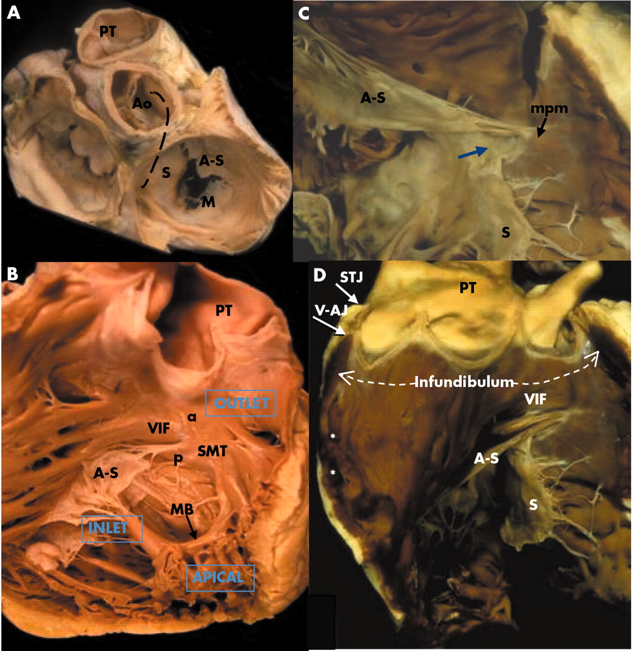
(A) This dissection of the cardiac base shows the central location of the aortic valve, wedged between the mitral and tricuspid valves, and behind the pulmonary valve. The broken line marks the curved ventricular septum. The leaflets of the tricuspid valve are designated septal (S), antero-superior (A-S), and mural (M). (B) The septal aspect of the right ventricle is displayed to show the septomarginal trabeculation (SMT) with its anterior (a) and posterior (p) arms embracing the ventriculo-infundibular fold (VIF). The moderator band (MB) crosses the ventricular cavity as a distinct bundle. (C) The commissure between antero-superior and septal leaflets is supported by the medial papillary muscle (mpm). This heart lacks formation of leaflet tissue in the region of the membranous septum (arrow). (D) This dissection of the outflow tract shows the muscular infundibulum supporting the pulmonary valve. Septoparietal trabeculations (asterisks) are flat. The semilunar leaflets have been removed to reveal the hingelines crossing the ventriculo-arterial junction (V-AJ) and rising to the sinutubular junction (STJ). Abbreviations as in fig 1.
Viewed from the diaphragmatic aspect of the heart, the right and left ventricles can be seen to lie side by side. The term “crux” of the heart (crus cordis) refers to the intersection between the planes of the atrial and ventricular septa upon the inferior atrioventricular junction. However, close examination will show the crux is not a perfect cross since the right atrioventricular junction is inferior to that of the left.1 Nevertheless, this view shows how the four chamber echocardiographic plane can be achieved. The most inferior sections will traverse the coronary sinus running alongside the inferior wall of the left atrium (fig 1).
STRUCTURE
The ventricles extend from the atrioventricular junction leftward to the apex and cephalad to the ventriculo-arterial junction. For the right ventricle, the hingelines (annuli) of the leaflets of the tricuspid and pulmonary valves delimit the chamber at the respective junctions with the atrium and the arterial trunk. The cavity of the chamber can be described in terms of three component parts: inlet, apical trabecular, and outlet as suggested by Goor and Lillehei (fig 2B).2 In the analysis of congenitally malformed hearts, this tripartite concept is more useful than the traditional division of the right ventricle into sinus and conus components. In malformed hearts, one or more of the three components may be lacking in one ventricle. The affected ventricle is usually smaller than its counterpart on the other side but is also incomplete and described as rudimentary. Very rarely, the heart contains only one ventricular chamber—the truly univentricular heart with a solitary ventricle.
In all hearts, it is the apical trabecular component that allows direct distinction between morphologically right, left, or indeterminate ventricles irrespective of the location of the chamber within the ventricular mass. The muscular trabeculations in the apical part of the morphologic right ventricle are coarser than those in the left ventricle. The apical trabeculations of the left ventricle are fine and display a criss-cross pattern. In both ventricles, the wall at the very tip of the apex is remarkably thin. Often, only 1 mm of or so of muscle separates the ventricular cavity from the epicardium. The third variant, the morphologically indeterminate ventricle is also the solitary ventricle. This form has trabeculations that are coarser than those found in a morphological right ventricle.
The inlet portion of the right ventricle extends between the atrioventricular junction as marked by the hingeline of the tricuspid valve to the insertions of the papillary muscles to the ventricular walls (fig 2B). In other words, it is the portion containing the tricuspid valve. Generally having three leaflets, sometimes the divisions between leaflets are not clear or some leaflets have scallops, leading some authors to conclude that the term tricuspid is not justified.3,4 Nevertheless, one of the three leaflets is distinctive of the tricuspid valve. Named the septal leaflet, this has multiple tendinous cords attaching it directly to the ventricular septum. This feature, together with its hingeline being closer to the ventricular apex than that of the mitral valve, the septal leaflet allows the echocardiographer to designate the ventricle as having right morphology (fig 1E). At its antero-superior part, the hingeline bisects the membranous septum dividing it into atrioventricular and interventricular portions. Not infrequently, there is a gap in the leaflet at the site of the membranous septum (fig 2C). A small papillary muscle, the medial papillary muscle supports the “commissure” between the septal and antero-superior leaflets. The latter leaflet is large and deeper than the septal leaflet. It is supported in its mid portion by a large papillary muscle that usually arises from the moderator band close to its insertion to the parietal wall. The third leaflet, the inferior leaflet (also known as the mural or posterior leaflet) is supported by several small papillary muscles which arise from the diaphragmatic wall of the right ventricle. The variability in number and arrangement of papillary muscles also distinguishes the tricuspid valve from the mitral valve which has a more regular arrangement of two groups of papillary muscles supporting it.
The pulmonary valve is separated from the tricuspid valve by a muscular fold, the ventriculo-infundibular fold. The fold forms the supraventricular crest at its septal margin where it inserts between the anterior and posterior limbs of the septomarginal trabeculation (fig 2B,D). From its septal margin, the fold continues superiorly into the subpulmonary infundibulum of the right ventricular outlet. The antero-superior wall of the right ventricle completes the muscular tube known as the subpulmonary infundibulum that leads to the pulmonary valve (fig 2D). Significantly, it is possible surgically to detach the infundibulum so as to harvest the entirety of the pulmonary valve for use as an autograft in the Ross procedure without incursion into the left ventricle.5 Thus, the infundibulum lifts the pulmonary valve clear of the ventricular septum. The semilunar hingelines of the pulmonary valve cross the anatomic junction between ventricular muscle and the fibro-elastic wall of the pulmonary trunk (fig 2D). In this arrangement, small segments of infundibular muscle are enclosed within the three pulmonary sinuses. The apices of the hingelines attach to the sinutubular junction that demarcates the juncture between the sinuses and the tubular portion.
The subpulmonary infundibulum is usually free of muscular trabeculations. Proximally, however, a clear cut demarcation between outlet and apical portions is absent since trabeculations running from the septum to the parietal wall are frequently found (fig 2D). These septoparietal trabeculations can be flat, hugging the parietal wall, or more prominent and hypertrophied as in hearts with tetralogy of Fallot, contributing to muscular subpulmonary stenosis.
The ventricular septum is muscular apart from a very small fibrous portion that is the membranous septum. Ventricular septal defects that occur in the environs of the membranous septum are described as perimembranous defects. Owing to the curvature of the ventricular septum in the normal heart (fig 2A), the right ventricle is described as wrapping around the left ventricle. However, the configuration of the left ventricular inlet and outlet portions does not allow the corresponding portions of the right ventricle to be superimposed upon each other. The overlap between left ventricular inlets and outlets puts the aortic outflow tract immediately behind the septum that separates it from the right ventricular inlet, reflecting the “wedged” position of the aortic root (fig 2A).
On the septal aspect of the right ventricle is a characteristic muscle band termed the septomarginal trabeculation (fig 2B). In some hearts it can be seen clearly as a Y shaped strap that cradles the ventriculo-infundibular fold between its arms. The medial papillary muscle inserts to the arm that is directed posterio-inferiorly. The other arm points antero-cephalad and blends into the subpulmonary infundibulum. Usually, but not always, the body of the Y is adherent to the septum. In sectional imaging, it can appear as a bump on the septum. When abnormally formed or hypertrophied, it can be a substrate for dividing the ventricular cavity into two chambers. The moderator band, another marker for the morphologically right ventricle, takes off from the body of the Y to cross to the parietal wall carrying within it a fascicle of the right bundle branch of the atrioventricular conduction system. The insertion of the medial papillary muscle is the landmark for the more proximal portion of the right bundle branch. From there, it descends like a cord in the subendocardium of the septomarginal trabeculation.
MUSCULATURE OF VENTRICULAR WALL
The myocardium is a complex three dimensional network of myocytes in a matrix of fibrous tissue. Each myocyte is long and thin and joined to its neighbour at the ends as well as at its side branches. There is then a predominant longitudinal orientation of the myocytes forming the myofibres. The architecture or gross arrangement of these myofibres have been studied over more than 300 years with somewhat different interpretations among investigators primarily owing to technical difficulties in “tracing” each myofibre network in three dimensions without disturbing adjoining fibres.6 Since these contractile bundles change the shape of the heart and generate the force of the pumping chambers during systole, a summary of the arrangement of myofibres in the right ventricle can help the echocardiographer in understanding its function. The superficial or subepicardial myofibres are arranged more or less circumferentially in a direction that is parallel to the atrioventricular groove and encircle the subpulmonary infundibulum (fig 3). On the sternocostal aspect, the superficial fibres turn obliquely toward the cardiac apex to cross the interventricular groove and continue into the superficial myofibres of the left ventricle. On the diaphragmatic aspect, superficial right ventricular fibres turn a slight angle toward the base to join left ventricular myofibres. At the right ventricular apex, superficial myofibres invaginate in spiral fashion to form the deep or subendocardial myofibres that line the cavity. The deep myofibres are longitudinally aligned, apex to base (fig 3). In the normal heart, the muscular wall of the right ventricle not including trabeculations is 3–5 mm thick.7 In this relatively thin wall circumferential and longitudinal orientations predominate. In contrast, the thicker left ventricular wall contains obliquely arranged myofibres, superficially and longitudinal myofibres in the subendocardium, but these sandwich predominantly circular myofibres in between. Interestingly, our study on the hypertrophied right ventricle in tetralogy of Fallot showed a change in architecture to resemble the sandwich pattern seen in the normal left ventricle.8

The upper panels are sequential dissections by Professor Damian Sanchez-Quintana, University of Extremadura, Spain. (A) A normal heart viewed from the front shows the circumferential to oblique arrangement of the myofibres in the subepicardium. (B) Myofibres lying deeper than the subepicardium retain the circumferential arrangement in the right ventricle but change from oblique to circumferential in the left ventricle. (C) The right ventricle is opened to show the longitudinally arranged subendocardial myofibres. The lower panels depict in simplistic fashion the subepicardial myofibres (left hand panel) and the deeper myofibres (right hand panel) in the ventricles of the normal heart. Abbreviations as in fig 1.
IMAGING WITH ECHOCARDIOGRAPHY: ANATOMICAL LANDMARKS
The location of the right ventricle behind the sternum restricts somewhat the transthoracic parasternal windows that can be accessed by the ultrasound beam. Thick trabeculations in the chamber may occasionally be confused with a thrombus or a tumour or be misdiagnosed as hypertrophic cardiomyopathy.9,10
Because of the complex shape of the right ventricle, triangular from the frontal aspect and crescentic from the apex, it is necessary to image the right ventricle from several projections, each characterised by specific anatomic landmarks.
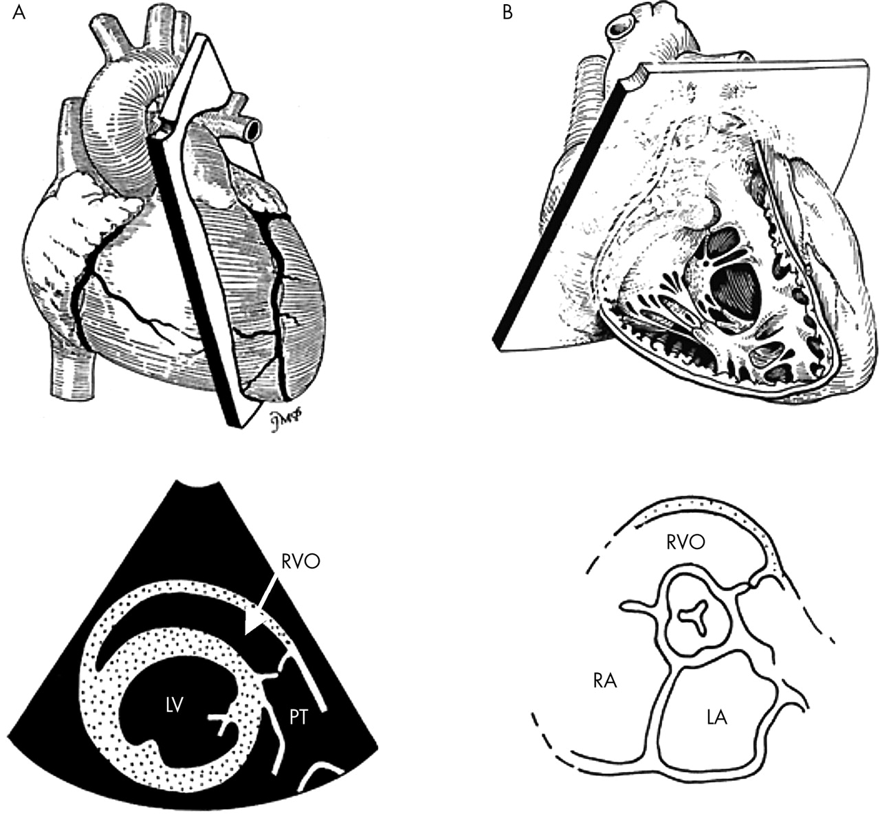
1. The parasternal long axis plane—This displays the right ventricular outflow tract which is usually a third of the normal left ventricle. The right ventricular free wall can be seen just in the front, but optimal gain settings may be necessary for its optimal visualisation. Posteriorly, the ventricular septum can be seen (fig 4). A standard normal structure that needs to be recognised from this projection is the moderator band, which links the ventricular septum to the parietal wall. It is important to recognise and exclude it when measuring the thickness of the ventricular septum.

Plane orientation for the parasternal long axis (top) with a corresponding tomographic view (bottom) demonstrating the position of the right ventricular outflow tract. The parasternal long axis plane incorporates the moderator band (MB) in the right ventricle.
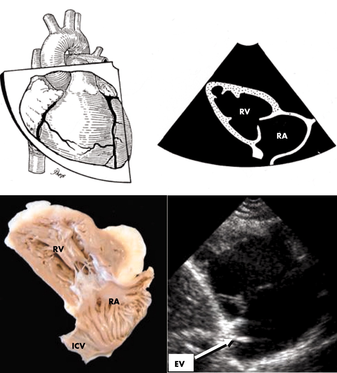
2. Right ventricular inflow tract—With the transducer tilted centrally towards the xiphoid, the long axis view traverses the inlet portion and allows assessment of tricuspid valve anatomy and function. From this projection, the apex is rarely captured (fig 5). Internal landmarks are the oblique position of the antero-superior and mural (posterior/inferior) leaflets in the centre of the image, dividing the “spade shaped” right ventricular inlet from the right atrium. Importantly, the Eustachian valve should be imaged from this plane, immediately behind the mural leaflet.

Plane orientation and corresponding images of the parasternal long axis view of the right ventricular inflow tract. Note the “spade shape” of the RV inlet and the position of the Eustachian valve behind the mural leaflet. RA, right atrium; RV, right ventricle; EV, Eustachian valve.
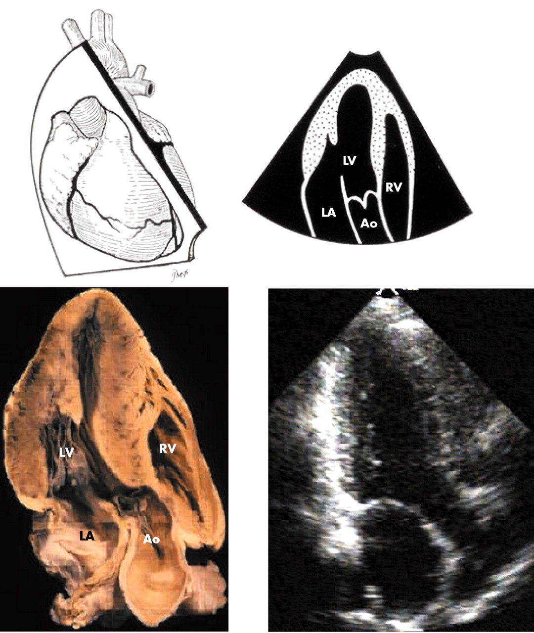
3. Right ventricular outflow tract views—Tilting the transducer upwards towards the left shoulder, the right ventricular outlet can be visualised, curving over the left ventricular outflow leading to the pulmonary valve (fig 6A). Two of the three pulmonary leaflets are visualised as very thin but highly mobile structures, similar to the aortic leaflets. Beyond the pulmonary valve is the pulmonary trunk (main pulmonary artery). Figure 7 displays a normal pulmonary valve in diastole and systole. The bifurcation of the pulmonary trunk into left and right arteries can also be visualised from this projection. Occasionally however, the transducer needs to be positioned higher up the chest wall to place the short axis cut of the aortic root in the middle of the picture (fig 6B).
Plane orientation and corresponding views of the right ventricular outflow tract. The RV outflow (RVO) appears curving over the LV (A). The RV outflow can also be seen from the basal short axis when the aortic valve is seen in the centre of the picture (B). LA, left atrium; LV, left ventricle; MPA, main pulmonary artery; RV, right ventricle.

Views of the right ventricular outflow tract (RVOT) show the pulmonary valve in diastole (A) and in systole (B).
4. Short axis planes—The short axis planes display the crescentic shape of the right ventricle. Sweeping to the level of the papillary muscles of the mitral valve allows the shape of the septum to be assessed throughout the cardiac cycle and inferences made of systolic pressure and diastolic volume overload in the right ventricle (fig 8).

Parasternal short axis plane at mid left ventricle demonstrating the crescentic shape of the right ventricle. Note within the RV cavity part of the tricuspid leaflet. The moderator band (*) is seen in the heart section.
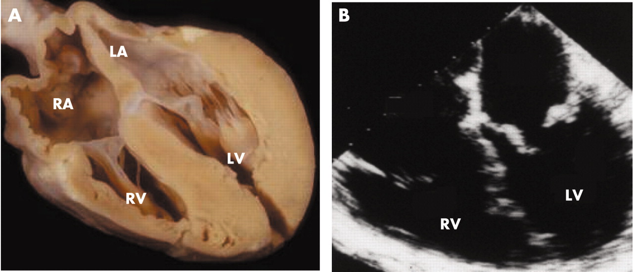
5. Apical four chamber projections—From the apical window, the four chamber view is best for morphological assessment as well as measurement of tricuspid valve and annular size and right ventricular dimension (fig 9). It displays the morphological features of the septum showing chordal attachments and lower hingeline of the tricuspid valve (nearer the apex), the raised profile of the septomarginal trabeculation, and the take-off of the moderator band that characterise right ventricular morphology. The tricuspid valve size correlates with right ventricular size in this view. From this projection, the crux of the heart is well seen with the respective atrioventricular connections. Pulmonary veins are also seen regularly at the back of the left atrium.

Apical four chamber plane demonstrating the four cardiac chambers. Notice the atrial septum (arrow) and the position of the tricuspid valve closer to the apex. It is also good for revealing morphological features of the septum, the septomarginal trabeculation (SMT) and moderator band (MB). LA, left atrium; LV, left ventricle; RA, right atrium; RV, right ventricle.
6. Apical long and two chamber views—From the apical four chamber position, rotating the transducer 90°, the apical long axis (or three chamber) view may be visualised (fig 10). This is an important addition to the apical four chamber section because of the optimal visualisation of the subvalvar mitral apparatus. Here, the entire length of the mitral leaflets should be seen, together with their respective tendinous chords attached to the papillary muscles (fig 10). Anteriorly, the triangular shape of the right ventricular outflow tract can also be visualised in a way similar to the parasternal long axis view. With 30° counter clockwise rotation, the true apical two chamber view can be seen displaying the inferior and anterior left ventricular free walls. Here the aorta should not be seen. This is a dedicated left ventricular projection and no right heart chambers are seen.
Apical three chamber (long axis) view demonstrating the long axis of the left heart. This plane displays well the mitral apparatus and also the right ventricular outlet in similar fashion to the parasternal long axis view.
7. Subcostal views—The subcostal approach is also important as it shows the diaphragmatic wall of the right ventricle, the right atrium, and the inferior vena cava (fig 11). It is also an excellent echocardiographic window in infants and children. It gives a slightly oblique four chamber view that provides information about the right ventricular inlet. The main utility of this projection is to visualise the atrial septum, which is cut perpendicularly. Thus atrial septal defects, patent foramen ovale, and other atrial pathologies can readily be identified from these projections.

Subcostal projection of the heart demonstrating all four cardiac chambers. Note the position of the atrial septum viewed perpendicularly to the ultrasound beam for optimal visualisation. It provides views of the right ventricular inlet that are slightly oblique to the four chamber view from apical or parasternal windows.
Rotating the transducer clockwise and tilting anteriorly will show the right ventricle in its short axis, revealing the moderator band and coarse trabeculations. Counter clockwise rotation will show the paracoronal view of the right ventricular outlet and pulmonary valve with the inlet part of the ventricular septum in the plane of the screen. The aortic root is tucked in between right ventricular inlet and outlets. This view is useful for showing the key features of tetralogy of Fallot since it profiles the antero-cephalad malalignment of the outlet septum and subpulmonary muscular stenosis (fig 12). The aortic valve overriding the septum can be seen through the ventricular septal defect.

(A) and (C) are subcostal projections from a patient with tetralogy of Fallot. Upper panel displays the image in echocardiographic view while the lower panel displays the same image in an anatomical orientation. The aorta is seen overriding the ventricular septum by about 50% and the curved arrow is through the ventricular septal defect. (B) and (D) show a heart specimen in similar orientations to the echocardiograms. The right ventricular outflow tract has been cut through and the outlet septum (*-*) divided. The characteristic malalignment of the outlet septum produces subpulmonary muscular stenosis of the right ventricular outflow tract (arrows).
8. Transoesophageal projections—The transoesophageal approach can give four or five chamber planes and planes that display the right ventricular inflow tract longitudinally (fig 13). It is used in assessing the right ventricle in congenital heart disease, but also may be very useful in adult patients with difficult transthoracic windows.

(A) and (B) are normal four chamber views as obtained from the transoesophageal approach.
THE NORMAL VALUES
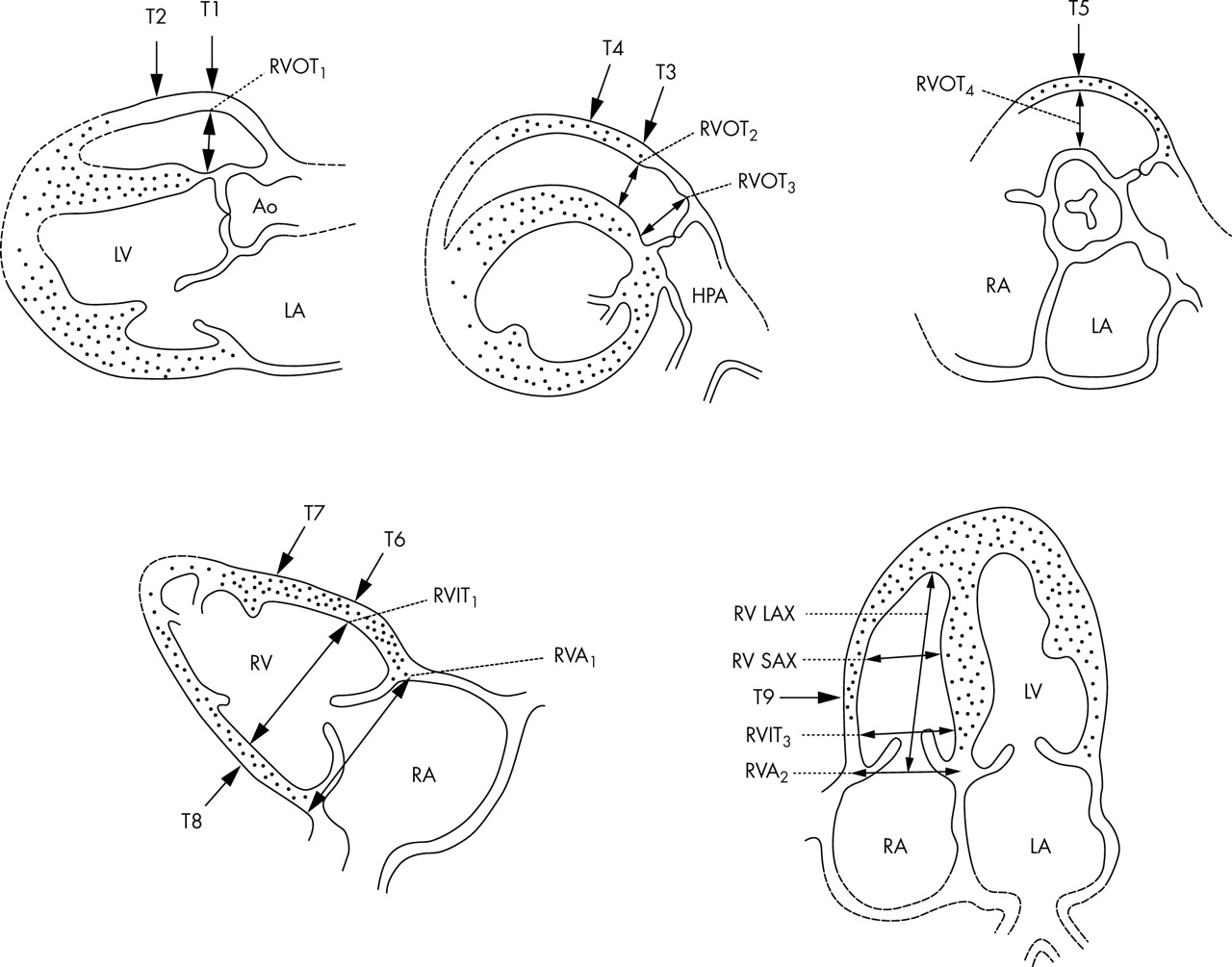
The right ventricular size and function has been a main focus of echocardiographers for many years as it can be affected both directly but also following left heart pathology. While most often the right ventricular size is compared to the left in relative terms, normal right ventricular values have previously been published for both thickness and dimensions.7 Tables 1 and 2 are adapted from Foale et al.7 Figure 14 displays the five most commonly used projections in order to assess the cavity size and wall thickness of the right ventricle.
Measurements of right ventricular chambers at the levels indicated on fig 14, at end diastole, in 41 normal subjects. Adapted from Foale et al7
Right ventricular wall thickness at end diastole of 41 normal subjects at the levels indicated on fig 14. Adapted from Foale et al7
The views and levels for measuring right ventricular chamber and wall thickness. See text for details. Reproduced with permission from Foale et al.7
CONCLUSIONS
The right heart may be challenging for any imaging modality because of its position and its thin walls. In echocardiography, the most widely used technique, imaging the right ventricle is often crucial for assessing severity of some left heart conditions and for detecting pathologies that affect primarily the right heart. Because of its shape and position behind the sternum, the right heart needs to be imaged from several echocardiographic windows to provide several cross sectional planes. This interrogation should be an integral part of the routine echocardiographic examination. Failure to do so may result in missing a number of abnormalities or underestimating severity of some pathologies of the left heart. Normal values are available for comparisons when assessing ventricular size and wall thickness.
Acknowledgments
Dr Ho acknowledges funding support from the Royal Brompton and Harefield Charitable Fund.
Footnotes
-
Competing interests: The authors wish to declare no competing interests.